Definity
CID
Contents
LAN Administration
Appendix a Screens Reference 243
Contents
Appendix B Private Networking 311
Appendix C Security Issues 403
Appendix G References 459
Issue Status
Purpose
Audience
Ethernet Data Module screen is changed in Release
Issue Status Preface
Screen Changes
Ethernet Data Module screen
Issue StatusPreface
Ppp Data Module screen
IP routing and the IP Route screen
Issue Status
Reorganization
Following chapter reorganization has been made for Release
Organization
Organization
Glossary
Index
Terminology
Terminology
Screen
Node
How to order more copies
How to access this book from the web
How to access this book from the web
Click Information Resources
How to Comment on This Book
How to Order Books
Tell us what you think
Tell us what you think
Where to Call for Technical Support
Where to Call for Technical Support
Telephone Number
Trademarks
Trademarks
Trademarks
Definity Switch Connectivity
Connectivity Overview
What kinds of connections are possible? Trunks
Networks
Definity Switch Connectivity Networking Overview
DCS-signaling data
Call-signaling data
Switch
Definity
Function of each circuit pack shown in is described below
Tie-Trunk Circuit Packs
IP-Interface
Pre-R7 circuit packs PI si only
Netcon si only
Qsig
Isdn
LAN
PPP
Release 8 Hardware Requirements
Hardware Requirements for Upgrades from Pre-R7 Switches
Connection Type Hardware Required
Pgate TN577
R8csi model
R8si model
Definity ECS
Definity Connection types and capacities
R8 Model Connection Type Endpoint
ISDN-PRI DCS+
Csi
ISDN-TSC
Pgate LAN
IP Softphones Networking Overview
IP Softphones
Telecommuter application
Road-warrior application
IP Softphones Networking Overview
IP Addressing
Physical Addressing
Logical Addressing
Class a
128
50% Class B
25% Class C
1 to
Network ID Range Host ID Range Total IP Addresses
128.0 to
192.0.0 to
How subnets are created
Subnetting
Class Type Network ID Host ID
Default Subnet Mask
Class Type Network ID Subnet ID Host ID
11111111.00000000.00000000.00000000 255.0.0.0
Class-C subnets
No. Binary Subnet
Decimal
Bit subnets
Example
255 224
Subnet mask
11100000
Digits
Class a Class B Class C Default
Security Alert
Default Gateway
When to use IP routes
Connection When IP Routes are Needed Type
PPP
Route Type host
DS1
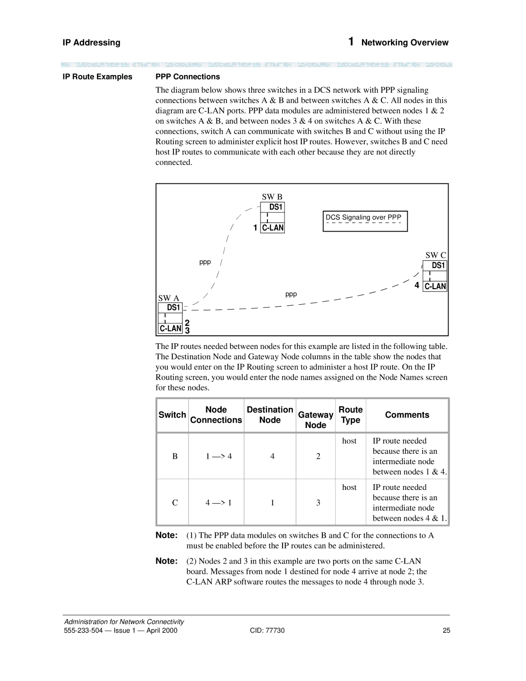
Switch Node Destination Gateway Route Comments Connections
LAN
IP Route Examples PPP Connections
PPP with Ethernet Connections
DS1
Default gateways for nodes 2 and 7, respectively
SW C
SW B
SW a
Ethernet-only Connections
IP route needed because
Issue 1 April
IP Solutions
Circuit Pack Requirements Software IP Solutions
Overview
IP Softphones
IP-Connected Trunks
Overview 323 Trunks
Trunk
Trunk Administration
Enabling Administration
Trunk Administration 323 Trunks
IP Parameters
Maintenance-Related System Parameters
UDP Port Range Min Max
Codec Bandwidth Requirement
Described in the next section
Trunk Administration Task Summary
Node names
IP Interfaces
2 Administered NCA TSC Assignment
Signaling Group
~ PBX ID
Trunk Group
Trunk Administration Task Detail
Task 1 Assign Node Names
Network Regions
Go to page 2 of the screen
Field Conditions/Comments
Task 1 Steps
Task 2 Define IP Interfaces
Enter c-lan or medpro
Task 2 Steps
Trunk Administration 323 Trunks Field Conditions/Comments
Task 3 Steps
Task 3 Assign Link via ethernet Data Module to the LAN
Task 4 Steps
Task 4 Create a signaling group
Configuration 4, for instructions Submit the screen
Are described in the Administrator’s Guide
Trunk Administration2 H.323 Trunks
Task 5 Create a trunk group
Open new Trunk Group form enter a tr n
PBX ID
If using DCS, go to screen
Enter group members
Open the Signaling Group form enter ch sig
Task 6 Modify signaling group
Enter values
Task 6 Steps
Task 7 Steps
Task 7 Specify codecs
Trunk Problem Solving
Troubleshooting IP Solutions
Troubleshooting IP Solutions 323 Trunks
Signaling group assignments
TGB1
TGA1
SGB1
SGA1
IP Softphone Problem Solving
Supported Switches and Adjuncts
LAN Administration
Overview LAN Administration
Checklist for Prerequisite Administration
Checklist Item
Otherwise
Overview LAN Administration Checklist Item
Configurations
Task Summary
Organization of this chapter
Supported Switches and Adjuncts
CMS LAN Setup Summary
Intuity Audix LAN Setup Summary
Configuration 1 R8r -ppp- R8si
Configuration 1 R8r -ppp- R8si LAN Administration
Task Summary
Configuration
Prerequisite Administration
Software-defined connections
Hardware connections
Steps
Switch 1 Task Assign Node Names
Open Data Module form enter ad da n
Switch 1 Task Assign Link via ppp Data Module to Switch
COR
COS
BCC
CHAP?
Switch 1 and specifies the destination node and machine ID
Switch 1 Task Assign Processor Channels
Configuration 1 R8r -ppp- R8si
Open the Processor Channel Assignment form enter ch com p
Local Session number on this switch must equal
Switch 2 Task Assign Node Names
This data module is assigned the next available extension
Switch 2 Task Assign Link via ppp Data Module to Switch
This is a display-only field
Open the Processor Channel Assignment form enter ch com p
Switch 2 Task Assign Processor Channels
End
Enable links and processor channels
Definity ECS R8r
Ethernet
Definity ECS R8csi
Task Summary
Configuration
See CentreVu CMS Software Installation and Setup
Switch 1 Task Assign IP Interfaces
End
Open Data Module form enter a da n
To CMS
Name entered on the Node Names screen
End
Open the Maintenance-Related System Parameters form enter
Switch 2 Task Enable Bus Bridge Connectivity
Node-4 Interface on the router to the subnet of Switch
Switch 2 Task Define IP Interfaces
Switch 1 Task Assign IP Interfaces page 77 for an
Add data next
Ip n
Switch 2 Task Assign IP Route to Switch
Configuration 2 R7r +CMS -ethernet- R7csi LAN Administration
Switch 2 Task- Assign Processor Channels
For this connection. The Destination Port number on
Definity ECS administration
Intuity System Administration
Network Addressing
Intuity system administration
Administer Extension Numbers, Channels Services
Administer Subscribers
IP Address 192.168.1.125
IP address administered on the Lucent Intuity system
Worksheet B LAN Data for the Lucent Intuity System
Enable links and processor channels
R8si BX.25
Hub
Ethernet node-3 Definity ECS R8si
Definity ECS R7si Definity ECS R7r
Name IP Address Default Node-1 192 Node-3
Switch 1 Task Assign pdm Data Module
Configuration 3 R8si-x.25 R8r Gateway LAN Administration
ITC
Ethernet- R8si Field Conditions/Comments
Configuration 3 R8si-x.25 R8r Gateway
Switch 1 Task Assign Link via x.25 Data Module to Switch
DTE/DCE
106 CID
Configuration 1 R8r -ppp- R8si
Add data module next
Ch com p
For each connection, the Local Session number on this switch
Issue 1 April CID 111
112 CID
Wideband transmission
For the call setup. Enter y when administering the data
Open Processor Channel Assignment form enter
116 CID
Switch 3 Task Assign Node Names
118 CID
Configuration 1 R8r -ppp- R8si
120 CID
Open Processor Channel Assignment form enter ch com p
Switch 3 Task Assign Processor Channels
122 CID
Enable links and processor channels
ECS R8si
Ppp Definity ECS R8csi
R8csi
Definity ECS R7csi Definity ECS R7si
126 CID
Extension in the dial plan Enter values
Node Name Name entered on the Node Names screen
Switch 1 Task Assign Processor Channels
130 CID
Must equal the Remote Session number on the remote switch
TSC
Ch sig n
NCA-TSC
134 CID
LAN Administration Ppp- R8csi
Switch 1 Task Assign ISDN-TSC Gateway
Configuration 4 R8csi -ISDN- R8si Gateway
Open the Isdn TSC Gateway Channel Assignment form enter
NCA TSC
As-needed means the administered NCA-TSC will be
138 CID
Switch 3 Task Enable Bus Bridge Connectivity
140 CID
Switch 3 Task Assign Link via ppp Data Module to Switch
Extension in the dial plan Enter values
Is complete that is, until after all data modules
Name Be a name entered on the Node Names screen
For this connection. This number must match the Destination
144 CID
Enable links and processor channels
Ethernet Hub
Review checklist Switch 1 administration Assign node names
Node-3 Ext
Configuration 5A
148 CID
Digits Node Name node-2 CHAP? n
150 CID
Switch 1 Task Assign IP Interfaces
152 CID
Open Data Module form enter a da n
Open the Processor Channel Assignment form enter
Issue 1 April CID 155
156 CID
Issue 1 April CID 157
Name IP Address Default Node-1-ppp 192 Node-2 Node-3 192
Bearer Capability Class. This is a display-only field
BCC
160 CID
Switch
162 CID
See IP Routing page 251 in Appendix a for more
Switch 2 Task Assign IP Route to node-3
Name IP Address Default Node-1-eth 192 Node-2 Node-3
Switch 3 Task Assign IP Interfaces
166 CID
Open Data Module form enter a da n
168 CID
End
170 CID
PppDS1
Definity ppp ECS R8r
172 CID
Configuration 5B
Submit the screen1
Issue 1 April CID 175
176 CID
Switch 1 Task Assign IP Interfaces
178 CID
Open Data Module form enter a da n
Switch 1 Task Assign Link via ppp Data Module to C-LANa
COS
Switch 1 Task Assign Link via ppp Data Module to C-LANb
Authentication Protocol security mechanism on this link
184 CID
Issue 1 April CID 185
Session Local
Must equal the Remote Session number on the remote switch
Switch 1 Task Assign IP Route C-LANa to node-3
Switch 1 Task Assign IP Route C-LANb to node-2
Issue 1 April CID 189
Name IP Address Default Node-1a-ppp 192 Node-2 Node-3
Digits Node Name node-1a-ppp CHAP? n
192 CID
Entered on the ppp Data Module screen
194 CID
System assigns the route number 4. Enter values
Name IP Address Default Node-1b-eth 192 Node-2 Node-3
Switch 3 Task Assign IP Interfaces
198 CID
Network uses 1’s
200 CID
End
202 CID
Networking Example
Overview Networking Example
Network Diagram
Ethernet 10BaseT Hub
Router
Isdn TSC
CMS
Link/Channel/TSC Map Networking Example
Link/Channel/TSC Map
ECS R6si ECS R8si
ECS R8csi
Network Map Networking Example
Network Map
R6si
R8r Gateway R8si
Switch-Node 1 Administration Networking Example
Switch-Node 1 Administration
Connection to Switch Node
DS1 Circuit Packs
Dial Plan Record
Dial Plan
Synchronization Plan
Signaling Group
Group 12 tie to Switch Node 2
Trunk Groups
Group 12 member Assignments
Group 22 Group Member assignments
Group 22 data to Switch Node 2- page1
Group 13 member Assignments
Group 13 ISDN-PRI to Switch Node
Group 14
Group 14 tie to Switch Node 4
Group 24 member Assignments
Group 24 data to Switch Node Page1
AAR Digit Analysis
Uniform Dialing Plan
Isdn TSC Gateway Channel Assignment
Routing Patterns
Pattern
Node Names
Data module
Data Modules
Ppp data module
Pdm data module
Ethernet data module
Processor Channel Assignments
Switch-Node 2 Administration Networking Example
Switch-Node 2 Administration
Group 12
Trunk Goups
Uniform Dialing Paln
Procr-intf data module
Release 6 Interface Links screen
Release 6 Processor Channel Assignment Screen
Hunt Group
Hunt Group
Switch-Node 3 Administration Networking Example
Switch-Node 3 Administration
Change synch
Group 13
Group 13 ISDN-PRI
String Min Max Pattern Type Num Reqd 221 101 Aar 222 224
Mrk Lmt List Digits Digits 113 User
Switch-Node 4 Administration
Switch-Node 4 Administration4 Networking Example
Bus Bridge
Switch-Node 4 Administration Networking Example
Group 14 member Assignments
236 CID
Change udp
Name IP Address Ppp41 192 Ppp14 CMS 192 Router 192 Ethernet1
IP Routing
240 CID
CMS Administration
Intuity Translations for DCS Audix
Intuity Translations for DCS Audix Networking Example
CMS Administration Networking Example
Networking Screens
Screens Reference
Screens Reference
Other Network-Related Definity Screens
Networking Screens
Networking Screens Screens Reference
Valid entries Usage
Pages 2
IP Address
Name
IP Interfaces
Valid Values Usage
Inter-region IP connectivity allowed?
Slot
Enable Eth Pt
Code
Sfx
Gateway Address
Valid Value Usage
Net Rgn
Network IP Routes
Connection When to Define IP Routes Type Host IP Routes
Route Number
Destination Node
LAN Board
LAN2
LAN1
Route Type
IP Media Parameters
Audio Codec
Preferences
Common Data Module Fields
Data Module Screens
Valid Entries Data Module Usage Types
Valid Entries Data Usage Module Types
Valid Data Module Usage Entries Types
Nncsspp
Port
Link
Valid Data Module Usage Values Types
Valid Data Usage Entries Module Types
TAC +
Switched
Establish Connection?
Dte, isn
Connected Data Module
Connected To
Test?
Unrestricted
Data Module Type
Valid Usage Entries
Common Fields Network uses 1’s for broadcast addresses?
Common Fields
Are not listed below
Networking Screens Screens Reference Valid Value Usage
Class a Class B Class C Default
Destination Digits
Chap?
Chap Secret
COS
Maintenance Extension
Hot-line , default , or
Physical Channel
List
Internal, external
External
Assigned Member Ext and Name Clocking
Specifies the data transmission rate for this connection
This form applies only to the r model
Set to adjunct for DCS, CMS, or Intuity Audix
Baud Rate
Default is
Sent without confirmation. Default is
Leave at 64 for normal operations
Page
Enter y if this PDM is the secondary data module used for
Enable
Communication-Interface Processor Channel
Proc Chan
Gtwy-tcp , mis , msaamwl
Audix , dcs , fp-mwi , gateway
Msaclk , msahlwc , msallwc
Msamcs , qsig-mwi , and blank
Interface Chan
Interface Link
Session Local
Destination Port
Session Remote
Mach ID
Hardware configuration
Reconfiguration
Circuit Packs
Carrier
Single-carrier-stack
Cabinet Layout
Carrier Type
TN802
Lgate
Screen for ISDN-PRI Facility Associated Signaling
Screen for ISDN-PRI Non-Facility Associated Signaling
Channels on its associated DS1 interface, and for no others
Type ISDN-PRI
Associated Signaling
Group Number
Primary D-channel
Max Number of NCA TSC
Secondary D-channel
Max number of CA TSC
Trunk Group For NCA TSC
Trunk Group for Channel Selection
Supplementary Service Protocol
Trunk Brd
Interface ID
Service/Feature
On pages 3-6 of the ATM Signaling Group screen
As-needed Inactivity Time-out min
Enabled
TSC Index
Local Ext
Through Can include up to 15 digits Blank
Networking ScreensA Screens Reference
Dest. Digits
Adjunct Name
H.323 signaling group type is used for H.323 trunks
Valid entries Usage 1719, 1720 or
5000-9999
65535
Valid entries Usage Mulaw or alaw
Valid entries Usage Or etsi
Valid entries Usage PROGress default ALERTing
Valid entries Usage T1 or E1
Valid entries Usage Host , network , or pbx
Sig Group
Isdn TSC Gateway Channel Assignments
Application
Other Networking-Related Definity Screens
Communication Interface Links
Other Networking-Related Definity Screens Screens Reference
Ext
Est Conn
Destination Number
Conn Mod
Maximum Bit Rate
Data Module type netcon
Assigned Member Ext
Special Dialing Option
Abbreviated Dialing
Data Module type analog-dm
Valid entries Usage Digits 0 through
Extended Trunk Access Call Screening
# character may only be used as
First character
EPN Code
Extension Number Portability Numbering Plan
Pages 1 through X of the Screen
Hop Channel Assignments Screen
Enter an interface link number in each field
Implementation notes
Chan for G3si
Network channel. Displays for G3si only
Partitioned Group Number
Node Number Routing
Node Number
Route Pattern
Routing Digits e.g AAR/ARS Access Code
Message Waiting Indication Subscriber Number Prefixes
Inserted Digits to form Complete Number
1 of the screen
Stratum
Port Network
Primary
Secondary
Location/Name
Slip
Ext Codes
Uniform Dial Plan
Ext Code, Type and associated data
AARCode ENPNode Local TempOOS UDPCode
Location Code
AARCode ENPNode Local TempOOS
310 CID
Private Networking
Contents of this Appendix
Distributed Communications System
Description of DCS
Distributed Communications System Private Networking
Attendant Control of Trunk Group Access
DCS Features
Alphanumeric Display for Terminals
Attendant Direct Trunk Group Selection
Automatic Callback
Automatic Circuit Assurance
Busy Verification of Terminals and Trunks
DCS Call Coverage
Call Coverage
316 CID
Call Waiting
Call Forwarding
Distinctive Ringing
Leave Word Calling
Multiappearance Conference/ Transfer
Trunk Group Busy/Warning Indication
DCS with Rerouting
How to administer Enhanced DCS
Italian DCS Protocol
Form Field
DCS Over ISDN-PRI D-channel
ISDN/X.25 gateway
How to administer DCS Over ISDN-PRI Channel
NCA-TSC
DCS feature considerations
DCS Over ISDN-PRI
LWC considerations
Busy/Warning
CAS
DCS Interactions
Operator ISDN-PRI
UDP
Busy Verification
CDR
Asai
GRS
SDN
Distinctive Ringing
Edcs
Example DCS configurations
Multiappearance
Conference/Transfer
Audix
PBX ID DCS?
TSC
FRL
TSC CA-TSC
PBX ID
PBX-ID
Switch
Group # Grp Type Used for DCS? DCS Sig. Method
Ext Code Type Location
TSC Index Processor Application Channel
Matching Min Max Del Replacement Net Conv Pattern String
Group # Grp Type Used
DCS PBX ID NCA-TSC
For Sig Sig. Group
Local Enable Establish Dest Far-end Appl Index Ext
Dialed String Min Max Rte Call Type Node Num Pat
Group # Grp Type Used for DCS Sig. Method
How to administer CAS
Centralized Attendant Service
ATM PNC?
ATM-PNC
CAS Backup Service
CAS Queues
CAS Remote Hold
CAS Outgoing Call Routing
Branch-generated call-identification tones
CAS Incoming Call Routing
Considerations Branch Attendants
Interactions
342 CID
InteractionsNone
How to administer Emergency 911 Calls
Extended Trunk Access
Case #1
Case #2
Case #3
Case #4
Abbreviated Dialing
Extension Number Portability
How to administer ENP
How to administer Inter-PBX Attendant Service
Inter-PBX Attendant Service
Private Network Access
How to administer Private Network Access
Aplt ISDN-BRI ISDN-PRI
Attendant Call Waiting
How to administer UDP
Distributed Communications System Private Networking
Extension
Switch RNX UDP Code
Considerations
354 CID
How to administer Isdn Feature Plus
Isdn Feature Plus
Isdn Feature Plus Private Networking
~ G3 Version field to ~ Isdn Feature Plus field to y
Differences in Inserted Digits field
Description
Interactions
Interrogation
Forwarding and Coverage
Qsig
Qsig Category Supported Features
Qsig Basic Supplementary Services
Qsig Basic Call Setup
Transit switch information
Transit Counter ANF-TC
Isdn numbering formats
Tandem switch information
Diversion
Call Transfer
Call Completion
Call Offer
SS-CC Options
Qsig Centralized
Other Qsig Centralized Messaging
What you get with Qsig Centralized Audix
What you do not get
Attendant Service
Qsig Centralized Attendant Services
Path Retention
Potential Drawbacks
Qsig Path Replacement
Qsig Supplementary Services with Rerouting
Qsig CAS functions in RLT-CAS
Qsig CAS functions not in RLT CAS
Qsig Value-Added Lucent Valu
Qsig Transfer into Lucent Qsig Voice Mail
Rerouting
Transfer into Qsig Voice Mail
Temporary Signaling Connection TSCs
Qsig Protocols
CA-TSC DCS only
Protocol standards
Qsig capabilities
Setting Up Qsig
~ Basic Call Setup field is y
~ Async. Transfer Mode ATM Trunking field is y
~ Basic Supplementary Services field is y
~ ISDN-BRI Trunks field is y
Numbering Format public, private, unknown, unk-pvt
Setting Up Qsig Supplementary Services
Transfer into Voice Mail
Setting Up Centralized Steps Attendant Services
Coverage with Qsig Diversion with Rerouting
Setting Up Qsig Valu Steps Call Coverage
Related Hunt Group Administration
Related Administration Terminating Extension Groups
Related Phone
Calling Party Number to AUDIX? y
Call Forwarding Diversion
Qsig Interactions
Transfer Into Qsig
Path Replacement
Voice Mail
Qsig Name
Transit Counter
382 CID
Indications
Message Waiting
Isdn Qsig BRI
Adjunct Switch Applications Interface Asai
Isdn Qsig
Called/Busy Name
386 CID
Service CAS
388 CID
Attendant Release Loop Operation
390 CID
Qsig
392 CID
Extending a Call
394 CID
Configuration requirements
Centralized Voice Mail Via Mode Code
Centralized Voice Mail Via Mode Code Private Networking
Definity ECS R8
Centralized Voice Mail Via Mode Code Example Configuration
Feature Support
~ Group Type field is Isdn ~ Service Type field is TIE
Setting Up Centralized Voice Mail Via Mode Code
~ Uniform Dialing Plan field is 4 for each node
~ Uniform Dialing Plan field is 4 or
~ Set Network Level field is
~ Call Type field is lev0
~ Type field is vmi
End
Japan TTC Q931-a Private Networking Protocols
Overview
Japan TTC Q931-a Private Networking Protocols
TTC Q931-a Protocols
Setting Up TTC Q931-a
~ Interface peer-master or peer-slave
~ Numbering format public, private, unknown, unk-pvt
Network Security Issues
Security solutions
Security concerns
Access control network topology
Network Security Issues
Private network
Private segment
Damage control application restrictions Summary
406 CID
Capacities and Resource Requirements
For Definity Capacity Limits
508
For C-LAN Number of Sockets Required
Capacities and Performance
Performance
Overview
Definitions
G3r G3si
POE =
57% 65% 52% 60%
Boards =31
Number CL m MedPro For GOS = P001
Number of MedPros needed
For Full Availability
Problem
Solution
ExampleInternet Call Center
LAN Installation
LAN Installation
Install the C-LAN Circuit Pack
Enter change system-parameters maintenance
Insert C-LAN Circuit Packs
Required. See the figure below
Install C-LAN Cables Hub connection
Wall field connection
Other Hardware Upgrades
Title Document Issue Number
IP Trunk Installation
Administration overview
IP Trunk Administration
IP Trunk Administration IP Trunk Installation
Prerequisites
Plan call routing
Off-Premise Dialing at Remote Site
NT Tasks
420 CID
DS1 Circuit Pack
Definity administration procedures
Ami-zcs Ami-basic or hdb3
544 048
Robbed-bit Cas
Mulaw
Trunk Group
424 CID
Backing up configuration manager
Double-click the IP Trunk Backup Restore icon
Restoring IP trunk
Confirming the number of available ports
NT administration procedures
Click Show All Ports
Click the Dial/Routing Plan tab
None
Routing based on Line Numbers
Routing based on Dialed String
Incoming calls
Select Terminating
Stopping IP Trunk Service
Click on Control Panel Services
Starting IP Trunk service Change companding to A-Law
Alaw
Non-DCS Configuration
Procedures for Extension Dialing Between Sites
Line Search String Replace String
Line Search Replace IP Address String
DCS over IP Trunk IP Trunk Installation Administration
Signaling
DCS over IP Trunk
TCP/IP signaling
IP Trunk Network Configuration
On Switch a
On Switch B
On Switch C
Line
Line Search Replace String
Search
Rerouting calls when IP transmission quality is poor
Click Properties
Click Monitor and Pstn Fallback
Setting up alerts on IP trunks
Placing a test telephone call
More information
Administration, consider making this a joint activity
Click Start, Programs, Administrative Tools
Viewing error messages
Testing Alerts
Alert types
Troubleshooting IP trunk
Check physical
Check LAN functions
Use traceroute to
Maintaining the performance of the IP trunk server
Configuration Wizard
Configuring Microsoft NetMeeting on a PC
Providing general
Information for
IP Trunk Installation Administration
Changing Audio Settings
DCS over IP Trunk
Making Calls to the IP trunk application from NetMeeting
Troubleshooting IP Trunk
Viewing error messages
Field Field Name Field Value Code
IP Trunk Worksheets
IP Trunk Worksheets
Worksheets
Worksheet
Fill in with Same Create Different
IP Trunk
Worksheets
1A2BX 1CX
Replace string 1F1A 2F2A
1AX
458 CID
Basic Definity ECS documents
References
Definity ECS Release 8.2 Reports, 555-233-505, Issue
BCS Products Security Handbook, 555-025-600, Issue
References
References
Definity ECS
Call center documents
CentreVu Call Management System CMS
Application-specific documents
Definity ECS Release 7 Console Operations Quick Reference
Console operations
ADU
AAR
Ansi
Aplt
Awoh
ATM
BB8ZS
B8ZS
BCC
BER
BRI
BOS
Ccitt
Ccis
Ccms
CDR
CMS
Cmdr
COS
COR
CSN
CSU
Dciu
DCE
DCP
DCS
DNS
Did
Dtdm
DSU
DTE
EIA
HDB3
FAS
Inads
Iana
Base address
Interserver routing table Glossary
IP Internet Protocol address
IP user
LAP-D
MAC
Mapd
MA-UUI
MIB
MDR
Mmch
MSA
Netcon
Nema
Nfas
NIC
Paccon
OSI
PDM
Pgate
PRI
Pstn
Psdn
PSN
Qppcn
RTP
RPN
Smdr
Simple Network Management Protocol Snmp Glossary
Snmp
SPE
TCP
TCP/IP
TDM
UDP
UNP
VCI
WAN
VPI
Zero Code Suppression ZCS
ZCS
Index
492 CID
Index
DS1 208, 228, 233 per system
314
299
383
369
498 CID
Qsig NCA-TSC
149, 159, 175, 180, 182
326
502 CID
We’d like your opinion