Flexible Motion Controller
FQM1 Series
Page
Omron
Omron Product References
Page
Table of Contents
Coordinator Module Functions 123
Inspection and Maintenance 259
Table of Contents
About this Manual
Name Cat. No Contents
Xii
Precautions
General Precautions
Safety Precautions
Intended Audience
Safety Precautions
Operating Environment Precautions
Application Precautions
Xvii
Xviii
Conformance to EC Directives
Conformance to EC Directives
Applicable Directives
Concepts
Countermeasure Examples
Current Characteristic Required element
Relay Output Noise Reduction Methods
Countermeasures
Name Model Cable length
Circuit Current Characteristic Required element
Charge the capacitor
Data Backup
Module Data Data backup
Temperature Initial After 5 years After 10 years
Backing Up DM Area Data in Flash Memory
Xxiv
Section
Section
Outline of FQM1 Flexible Motion Controller
Special I/O Servo Driver Pulse or Analog I/O Basic I/O
FQM1 Configuration
FQM1-MMP21
FQM1-MMA21
CJ1W-PA205R
Details
Modules
PLC
Outline of Internal Data Exchange and I/O
CX-Programmer
CX-Programmer
Systems
Expanded System Configuration
System Configuration
Serial Communications
Host Link System
Yes See note
FQM1
Serial Gateway
1N Connection between CJ1M and FQM1 Controllers
Connection between CJ1M and FQM1 Controller
No-protocol Custom Communications System via RS-422A Port
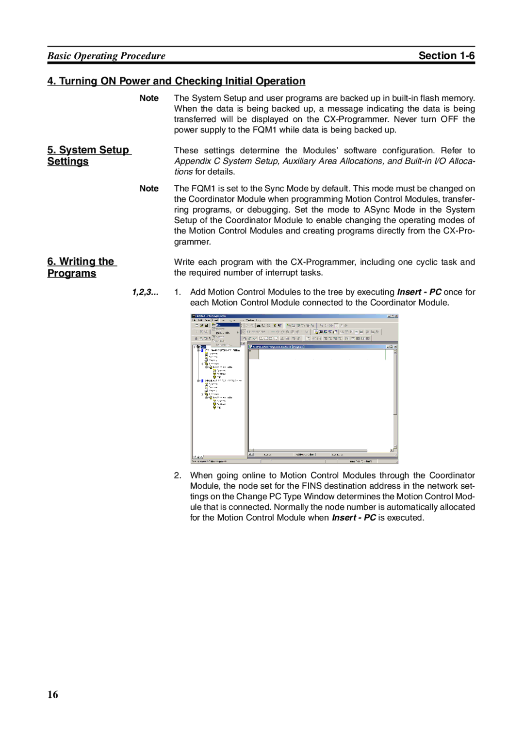
Basic Operating Procedure
Input wiring
Output wiring
Installation
Wiring Initial Hardware Settings
Examples
Writing the Programs
Transferring the Programs Testing Operation
Online Editing
Time Chart Monitoring
Save and Print the Programs
Data Tracing
Purpose Operation Function used Details
Function Tables Arranged by Purpose
Function Tables Arranged by Purpose
Purpose Operation Main functions Details Used
Position and Speed Control
Absolute Encoders
Analog Outputs
Pulse Output Function Procedures
Measuring Input Pulses
High-speed Analog I/O Control
Analog Input Function Specifications
Pulse Outputs
Controlling Timing
Input Interrupt Mode
Time Measurement with the Pulse
Section
Specifications and Nomenclature
Name Type Model Specifications
General Specifications
General Specifications
Must be installed
VA max Inrush current At 100 to 120 V AC See note
Power Supply Unit Specifications
Nomenclature
Indicators
Indicator Color Name Status Meaning
Coordinator Module
Function Specifications
Switch on Front Panel
Peripheral Port Baud Rate Detection/System Setup Switch
Bits TR0 to TR15
Built-in General-purpose I/O
Specifications
Motion Control Modules
Motion Control Module
FQM1-MMA21 Analog I/O
OUT7
MMP21
Performance Specifications
MMP21
MMA21
Specifications
CW/CCW
Pulse I/O Specifications FQM1-MMP21 Pulse I/O
Pulse Inputs and Analog FQM1-MMA21 Analog I/O Specifications
Dimensions
FQM1-CM001 Coordinator Module
FQM1-TER01 End Module
Power Supply Units CJ1W-PA202
XW2B-80J7-1A Servo Relay Unit
Maximum Current Maximum Total Power Consumption
Module Current Consumption
Current Consumption for Each Module
Current Consumption for 24-V Systems
Example Calculation Current and Power Consumption
Combining Power Supply Units Motion Control Modules
Motion Control Modules
Areas Backed Up to Flash Memory
Memory Block Diagram
Motion Control Modules
Areas Backed Up by Super Capacitors
Section
Installation and Wiring
Accessibility for Operation and Maintenance
Installation
Installation and Wiring Precautions
Temperature Control
Improving Noise Resistance
Do not install the FQM1 in any of the following positions
FQM1 Orientation
Ing
Terminal Screws M4 1.2 N·m M3 0.5 N·m
Installation in a Control Panel
Wiring Ducts
FQM1 must be mounted inside a control panel on DIN Track
Assembled Appearance and Dimensions
Routing Wiring Ducts
PLC FQM1
Motion Control Module width 49 mm
Assembled Dimensions
Installation Dimensions
Coordinator Module width 49 mm
Installation Height
Connecting FQM1 Components
DIN Track Installation
Lock the pins on the backs of the Modules
PFP-100N/50N DIN Track
DIN Track and Accessories
DIN Track
PFP-100N2 DIN Track
Power Supply Capacity
Wiring
Wiring Power Supply Units
AC Power Source
Grounding
Terminal Screws
Crimp Terminals
FQM1
Crimp Terminals for Ground Wire
Connection Methods
2 RS-232C Port Wiring
WiringSection
Connector Pin Arrangement
Connecting to an IBM PC/AT or Compatible
Peripheral Bus Toolbus Serial Communications Mode
Applicable Connectors Coordinator Module Connector
IBM PC/AT or Compatible Connector 9-pin, Male
Direct Connection from RS-232C to RS-232C
RS-232C Port Specifications
Specification
Connection Example to Programmable Terminal PT
FQM1-CM001 Coordinator Module
Wiring Module Connectors
Connector Pin Arrangement
General-purpose I/O 40-pin Connector
Pin No Name
General-purpose I/O 26-pin Connector
FQM1-MMP21 Pulse I/O 40-pin Connector
FQM1-MM@21 Motion Control Modules
Pin Name
FQM1-MMA21 Analog I/O 40-pin Connector
Pulse Outputs
External Connection Diagrams
Input between 4 and 20 mA
Are outlined in the following tables
Wiring Examples
Connecting Pulse Inputs FQM1-MMP21 MMA21
Example
Power supply Encoder
FQM1-MMP21
Connecting Pulse Outputs FQM1-MMP21
Connectors
Wiring Methods
Connecting Analog Outputs FQM1 MMA21
Connecting Analog Inputs FQM1-MMA21
Wiring Servo Relay Units
Applicable Connector-Terminal Block Conversion Units
Recommended Wire Size
RS-422 Connector
Pin No Signal
Nomenclature and Functions
Lower Terminal Block Pin Arrangement
Upper Terminal Block Pin Arrangement
Switch Setting details
Signal Switches
Following screwdriver can be used when removing wires
External Dimensions
Wiring Screw-less Clamp Terminal Blocks
Wiring Method
Recommended Screwdriver
Model Manufacturer
Phoenix Contact Inc
Sysmac PLC
Wiring when Using Servo Relay Units
Example Servo Relay Unit Wiring
Upper Terminal Block Arrangement
Lower Terminal Block Arrangement
List of FQM1 Connecting Cables
Connecting Cable Models
Specifications Model
RS-422A Connecting Cables with 9-pin D-sub Connector
Wiring Precautions
Signal Wiring
Reducing Electrical Noise
OUT
External Wiring
Surge suppressor specifications Diode specifications
Inductive Loads
Connecting I/O Devices
Input Devices
COM +
VON ≤ VCC VR
Precautions when Connecting a Two-wire DC Sensor
Residual Voltage
Output Wiring Precautions
Output Short-circuit Protection
Transistor Output
Method
Add a control resistor as shown in the following diagram
Output Surge Current
Reduce the surge current
Operation
Outline
User Program
Memory
Coordinator Module Operation
System Setup Flash Memory
Refreshing
Servicing Contents
3 I/O Refreshing and Peripheral Servicing
Startup Initialization
User Program Area
Description of Each Area
Motion Control Module Operation
Memory System Setup Read/Write DM Area D00000 to D32767
System Setup Using CX-Programmer
Tab Settings
Ules. Refer to 5-4 Synchronous Data Refresh for details
Sync Mode Operation
Same time
Scan or at the specified sync cycle time. See note
Program
Operating Modes
Following tables list status and operations for each mode
Mode Cyclic task status Interrupt task status
Operating Modes
Mode Changes Cleared areas Retained areas
Power OFF Operation
Operating Mode Changes and I/O Memory
Power OFF Operation
Power Holding Time
Power OFF Timing Chart
Fixed Power OFF Detection Time
User-set Power OFF Detection Time
Description of Operation
Instruction Execution for Power Interruptions
Module Functions and Data Exchange
Sync and ASync Modes
Sync Mode
ASync Mode
Synchronous Operation between Modules
Method Outline Description
Data Exchange between Modules
Applications
Cyclic Refresh
Word Bits Details Address
Cyclic Refresh Area Details
Coordinator Module Cyclic Refresh Area
Motion Control Module Cyclic Refresh Areas
Bit
Cyclic Refresh Area Allocations
CM Coordinator Module MM Motion Control Module
Bits Details
Synchronous Data Refresh
Sync Cycle Time
Synchronous Data
Transfer time
Input or analog output value in the System Setup
Synchronous Data Link Bit Area
Ladder execution results data
Synchronization between Modules
Settings
System Setup Coordinator Module
Trol Modules
Interruption of the Sync
System Setup Motion Control Modules
DM Data Transfer
Prohibit System
Area
Settings Details
Make Auxiliary Area Settings
Executing DM Data Transfer
Cycle Time Settings
Constant Cycle Time Function
Turn on Request Bit Programming Example
Constant Cycle Time Function Enabled for Coordinator Module
Constant Cycle Time Function in Sync Mode
System Setup
Constant Cycle Time Exceeded Error Clear Bit
Auxiliary Area Words
Watch Cycle Time Function
Cycle Time Monitoring Function
Cycle Time Too Long Flag
Auxiliary Area Bits
Clearing Constant Cycle Time Exceeded Errors
Constant Cycle Time Exceeded Error Clear Function
Normal Operation
Program Protection
Operation Settings at Startup and Maintenance Functions
Specifying the Startup Mode
Tab Name Details Settings Default
Automatic Backup to Flash Memory
Password Protection
Flash Memory
Name Address Meaning
Diagnostic Functions
Error Log
Auxiliary Area Flags
Operation of FAL006
Failure Alarm Functions
Operation of FALS007
Coordinator Module Functions
Peripheral 232C 422A
Serial Communications
FQM1 supports the following serial communications functions
Protocol Connections Description
Serial Communications
Procedure
Host Link Communications
FQM1. Select the method that best suits your application
Type Header Name Function Code
Host Link Commands
Type Command Name Function Code
Fins Commands
CR+LF
Forced SET/RESET
Forced SET/RESET Cancel
No-protocol Communications RS-232C Port
End code setting Yes
Message Frame Formats
CR+LF
On the TXD236 and RXD235 instructions
NT Link 1N Mode
System Setup RS-232C Settings Host Link Port Settings
Setting Default Enabled
CIO 0080 to CIO 0089 CJ1M master to FQM1 slave
Serial PLC Links
Overview
Ule are shared with the CJ1M master as shown below
CJ1M Master Settings
FQM1 Slave Settings
Source Words and Number of Link Words
Function
Settings
Smart Active Parts Communications Settings
Settings Default Enabled
Smartstep
No-protocol Communications RS-422A Port
RS-422A Settings
Motion Control Module Functions
138
Main function Sub-functions Applicable Modules
Overview
OverviewSection
FQM1 Modules have the following functions
Executing Interrupt Programs
Interrupt Functions
Overview
Interrupt Priority
Enabling All Interrupts
DI802 instruction will disable all interrupts
Disabling and Enabling All Interrupts
Disabling All Interrupts
Overview of the Input Interrupt Function
Input Interrupt Specifications
Input Interrupts
Applicable Models
Input Allocated input bit Interrupt task number
Using Input Interrupts
Counter Mode
Input Interrupt Mode Procedure
Counter Mode Procedure
Application Example
Equipped with one interval timer each
Interval Timer Interrupts
Interval Timer Interrupt Modes
Using Interval Timer Interrupts
@STIM
Stim Interval Timer
Model Functions
Specifications
Pulse Inputs
Based on the counter PV
Pulse Inputs
Pulse Input Specifications
151
Pulse Inputs
Latch Input Specifications
Internal Circuit Configurations
Applicable Instructions
High-speed Counter Function Description
Pulse Input Function Description
Linear Counter
Reset Methods
Counter Operation Numeric Ranges
Circular Counter
Target-value Comparison Method
Phase-Z Signal Reset Input and Software Reset
Software Reset
Checking for High-speed Counter Interrupts
Range Comparison Method
Monitoring High-speed Counter Movement Mode
Word Bits Function Details
Tab Function Details
System Setup Function Details
Word Bit Function Details
High-speed Counter Procedure
Pulse Input Function Procedures
Target-value comparison interrupt
Mode 1 Procedure
Mode 2 Procedure
Procedure
Pulse Input Function Example Application
163
164
165
Example Latching High-speed Counter PV
Pulse Outputs
168
One-shot Pulse Outputs
All Pulse Outputs Except for One-shot Pulse Outputs
Instructions Ineffective during Pulse Output
Sible is also listed in the following table
Pulse Output Function Details
Mode Description
172
SPED88
Pulse Output Operations
PULS88
Dividing ratio
Precautions when Using Pulse Outputs
Target frequency
Set by user
One-shot Pulse Output Function
Formula
Target frequency Hz Actual output frequency
One-shot Pulse Output Specifications
Tab Function Setting
Word Bits Function Contents
Time Measurement with the Pulse Counter
Target-value Comparison Interrupts from Pulse Output PVs
Pulse Counter Timer Specifications
Linear Mode Operation
END ACC
Range Comparison Bit Pattern Outputs from Pulse Output PVs
Circular Mode Operation
Ms Cycle
12 PLS2887 Pulse Output Direction Priority Mode
Setting
Speed-change Cycle
Execute PLS2887 with A628.14 OFF
Pulse Output Function Procedures
Setting the Pulse Output Direction Priority Mode
Pulse Output Direction Priority Mode
Pulse output port
Pulse Outputs with Acceleration/Deceleration
Port Pulse output port
Electronic Cam Control Functions
187
One-shot Pulse Output STIM980
Pulse Counter Timer Function STIM980
@SPED
Pulse Output Function Examples
Accelerating the Frequency at a Fixed Rate
Changing the Frequency in Steps
Speed
Number of pulses is 0 or more
192
@PLS2
Using PLS2887 for Trapezoidal Acceleration/Deceleration
One-shot Pulse Output Function Example
Pulse Counter Time Measurement Timer Example
Supports continuous mode only
Pulse Output Starting Conditions
CCW
Use this function for positioning
SPED8 PULS8 PULS88
PULS886 Absolute Pulse Output in Progress
Case
Absolute linear
Target position Present position
Cases 7, 11, 12
Cases 6, 8, 9,
199
P is in ASCII. It is 50 hex in hexadecimal
Serial Data Specification
Data Format of Absolute Encoder Output
Data Format
Counting Operation Counter Operation Details
Counter Operation
Absolute Number of Rotations PV Counter 1 A604 and A605
Absolute Present Value
Absolute Linear Counter Absolute Circular Counter
Absolute Present Value Preset
Absolute Offset Preset
7FFF
Related Areas
Tab Function Details Time when Setting
Word Bits Function Details Controlled
Auxiliary Area
206
Acquiring Method
Overview of Absolute Encoder Output Data Acquire
Absolute Encoder
Output Data
208
Program Description
Sample Programs Connecting an Omron W-series Servo Driver
210
211
Axis
Virtual Pulse Output Function
Operands
Mode Specifier Sets the output mode
First Word of Setting Table
Axis Instruction For Virtual Pulse Outputs
Description
Positioning or Speed Control Using a Virtual Axis
Analog Input Functions
Motion Control Module for Analog I/O
FQM1-MMA21
Analog Input Function Specifications
Tab Function Settings Time when setting Becomes effective
Related Areas and Settings
Word Bits Function Settings Controlled
220
221
Signal Range −10 to 10 Signal Range 0 to 10
6 A/D Conversion Value
With END Refreshing With Immediate
Overview CTBL882 Instruction Operation
Signal Range 1 to 5 V and 4 to 20 mA
Signal Range 0 to 5
High-speed Analog Sampling FQM1-MMA21 Only
Comparison Table
At several measurement points
@CTBL
Analog Outputs
Analog Outputs
Analog Output Function Specifications
Overall accuracy is the ratio of accuracy to the full scale
CPU standby status
Condition Analog output
To 5
Specified Output Values and Analog Output Signals
END Refreshing With Immediate Refreshing
To 10
Procedure
Outputting the Analog Output Value Stored Auxiliary Area
Outputting a Stepped Analog Output
Outputting a Sloped Analog Output
231
232
Connecting the CX-Programmer
CS1W-CIF31
Make System Setup settings, and monitor or debug operation
Name Model Specifications
Cables shown in the following table
Connecting the CX-Programmer
System Configuration
Connecting a Personal Computer Running Support Software
CS1W-CIF31
Cable Connection Diagram
Connection Methods Using a USB-Serial Conversion Cable
Cable Port Communic Connecting Ations Connector Model
CX-Programmer Connecting Cables
Serial Features Communications Mode
Connecting an RS-232C Cable to the RS-232C Port
When connecting the CX-Programmer to the FQM1
Connecting an RS-232C Cable to the Peripheral Port
240
Error Processing
Instruction FAL numbers Error codes
Error Log
Errors Generated by FAL006/FALS007
Error Log Structure
Indicator Status and Error Conditions
Error Processing
Error Categories
Error Information
Prphl OFF COMM1 COMM2
Error Codes
Classification Error code Error name
ERR OFF
Error Processing Flowchart
CPU Standby
Error Tables
CPU Errors
Fatal Errors
247
Fatal Errors
Lit Flashing
Non-fatal Errors
Non-fatal Errors
C2FF
Other Errors
Power Supply Check
Program Error Check
Memory Error Check
System Setup Error Check
Cycle Time Overrun Error Check
11 I/O Setting Error Check
12 I/O Check
Environmental Conditions Check
Troubleshooting Problems in Modules
Coordinator Module Errors
Error condition Probable cause Remedy
Input Errors
Motion Control Module Errors
Output Errors
Inspection and Maintenance
Inspection Criteria Action
Inspections
Inspection Points
Inspection Points for Periodic Inspections
Tools Required
Module Replacement Precautions
Tools Required for Inspections
Required Tools
262
Programming Programs and Tasks
Tasks
Type of task Description
Type of subroutine Description Calling instruction
Using Normal Subroutines
Subroutines
What Are Subroutines?
Overview
Using Subroutines That Pass Parameters
Execution without Subroutine Input Condition Flags
Execution with Subroutine Input Condition Flags
JSB982 Operation
Address Corresponding subroutines Word Bits
JSB
Appendix a
Mcro
RET
Main Program
Instruction Conditions
Power Flow
Basic Information on Programming
Basic Information on Instructions
Operands
Instruction Description Setting Canceling Condition
Operand types Description Symbol
Flags
Word Addresses
Instruction Location and Input Conditions
Addressing I/O Memory Areas
Bit Addresses
Operand Description Notation Application
Specifying Operands
BCD
Operand Description Notation Application Examples
#FFFFFFFF
Data Operand Data form Symbol Range Application example
LD ,IR0
BCD
NUL NUL
Abcde
NUL
Abcd
Data Formats
Data type
Decimal Digit
Two’s Complements
Complements
7FFF
Decimal Hexadecimal Binary
Ffff
Fffe
Non-differentiated Instructions
Variation Symbol Description
Instruction Variations
Input Conditions
280
Programming Precautions
Using Condition Flags
Condition Flags
Using Execution Results in NC and no Inputs
CMP
Difu
Using Execution Results from Differentiated Instructions
Error Flag
Main Conditions Turning on Condition Flags
Negative Flag
Equals Flag
Carry Flag
Less Than and Greater Than Flags
Program section Instructions Instruction condition Status
Special Program Sections
Instruction Combinations
Subroutines
Following instructions cannot be placed in a subroutine
Instructions Not Allowed in Subroutines
Instructions Not Allowed in Step Ladder Program Sections
Instructions Not Allowed in Block Program Sections
FQM1 Operation Flowchart
Computing the Cycle Time
YES
Calculating the Cycle Time of the Coordinator Module
Overview of Cycle Time Calculations
Coordinator Module
Motion Control Modules
Cyclic Refreshing
Peripheral Service
Calculating the Cycle Time of a Motion Control Module
Sync Bus Refreshing
Model Refresh time
Module I/O Refresh Times
Cyclic Refresh Time in the Coordinator Module
Cyclic Refresh Time in Motion Control Modules
Calculation Example for FQM1-MMP21
Example of Calculating the Cycle Time
Online Editing Cycle Time Extension
Conditions
Response Time
Response Time
Coordinator Module I/O Response Time
Minimum I/O Response Time General-purpose I/O 0 to
Motion Control Module I/O Response Time
Input Interrupt Tasks
Interrupt Response Times
Motion Control Module Interrupt Response Times
Response Time for Pulse and Analog I/O
Scheduled Interrupt Task
Motion Control Module Interrupt Processing Times
Maximum Response Time
Processing Time
Interrupt Response Time Calculation Example
Minimum Response Time
298
Memory Overview of I/O Memory
Introduction
Parameter Area
Memory Structure
Coordinator Module
CIO
Motion Control Modules
Bit Area CIO 0000 and CIO
CIO Area
END Refresh
Refresh
Synchronous Data Link Bit Area CIO 0200 to
Serial PLC Link Bit Area CIO 0080 to CIO
Temporary Relay Area TR
Refreshing Using the IORF097 Instruction
Work Area W000 to W255 W000.00 to W255.15, 4,096 Bits
Auxiliary Area A000 to A649 A000.00 to A649.15
Timer Area
Appendix B
Counter Area
BCD-mode Addressing *D
Data Memory DM Area
Condition Flags
Binary-mode Addressing @D
Using the Condition Flags
Name CX-Programmer Function Symbol
Summary of the Condition Flags
Using the Clock Pulses
Name Label CX-Programmer Operation Symbol
Clock Pulses
Parameter Area
System Setup
System Setup in the Coordinator Module
Prohibit System Interrupt of the Sync Mode
Allow Writing to User Memory
Startup Mode Setting CX-Programmer Startup Tab
Cycle Time Settings CX-Programmer Timer/Peripheral Service
Appendix C
Peripheral Port Settings for Host Link
Peripheral Port Settings CX-Programmer Peripheral Port Tab
Host Link Unit Number
Peripheral Port Settings for NT Link
Peripheral Port Settings for Peripheral Bus ToolBus
Standard/Customer Setting
Format
RS-232C Port Settings for Host Link
RS-232C Port Settings for Peripheral Bus ToolBus
RS-232C Port Settings for NT Link
RS-232 Port Settings for No-protocol Communications RS-232C
Send Delay
Data Format
PLC Link Unit No. PC Link Unit Number
RS-232C Port Settings for PLC Link PC Link Slave
Start Code and End Code
Number of Received Bytes
Send Delay Time
Peripheral Service Time
Fixed Service Time Enable Setting Set Time to All Events
CX-Programmer Cycle Time Tab
System Setup in Motion Control Modules
Settings Used by All Motion Control Modules
CX-Programmer Module Settings Tab
CX-Programmer Pulse Input Tab
FQM1-MMP21 Motion Control Modules with Pulse I/O
Function Details
CX-Programmer Pulse Output Tab
FQM1-MMA21 Motion Control Modules with Analog I/O
Address Bits Function Remarks When setting
RS-232C Port Settings Host Link Port
Details on System Setup Settings
Startup Mode
Peripheral Port Settings
Messages Sent and Received with No-protocol Mode
Constant Cycle Time
Watch Cycle Time
Over
Fixed Peripheral Servicing Time
328
Auxiliary Area Allocations by Function
Allocations That Are the Same for All Modules
FQM1-MMP21 Motion Control Modules with Pulse I/O
330
331
332
333
334
335
FQM1-MMA21 Motion Control Modules with Analog I/O
337
338
339
340
341
342
Appendix C
Allocations Related to Built-in Inputs
System Flags
Program Error Flags
Other Error Flags and Bits
Error Log and Error Code
Module Errors
FAL/FALS Errors
Memory Errors
Errors
Communications
Other
Peripheral Port
Allocations Directly Related to Instructions
RS-232C Port
RS-422A Port
Motion Control Module Built-in I/O Allocations
Coordinator Module Built-in I/O Allocations
Appendix D
Appendix D
351
352
353
354
355
356
357
358
Detailed Explanations on the Auxiliary Area
Error Codes and Error Flags
Error Log Area A100 to A199
Classification Error code Meaning Error flags
FQM1 Memory Addresses
Memory Configuration
Memory Map
FQM1 Instruction Execution Times and Number of Steps
Sequence Input Instructions
Sequence Output Instructions
Timer and Counter Instructions
Sequence Control Instructions
Comparison Instructions
Data Movement Instructions
Increment/Decrement Instructions
Data Shift Instructions
Symbol Math Instructions
Logic Instructions
Conversion Instructions
Floating-point Math Instructions
Special Math Instructions
Table Data Processing Instructions
Data Control Instructions
Subroutine Instructions
High-speed Counter and Pulse Output Instructions
Interrupt Control Instructions
Refresh Instruction
Step Instructions
Other Instructions
Serial Communications Instructions
Debugging Instructions
Failure Diagnosis Instructions
If not
Else
Iend
374
Index
Index
377
378
379
Page
381
382
383
384
385
386
Revision code Date Revised content
Revision History
Original production
388
Regional Headquarters
Omron Corporation
Terms and Conditions of Sale
Omron Electronics LLC