FQM1 Series
OPERATION MANUAL
Flexible Motion Controller
FQM1-CM001 FQM1-MMP21 FQM1-MMA21
FQM1-CM001 FQM1-MMP21 FQM1-MMA21
Flexible Motion Controller Operation Manual
FQM1 Series
Produced November
Page
Notice
OMRON Product References
Visual Aids
OMRON,
Page
TABLE OF CONTENTS
TABLE OF CONTENTS
SECTION
TABLE OF CONTENTS
Inspection and Maintenance
SECTION
Appendices
TABLE OF CONTENTS
About this Manual
Page
PRECAUTIONS
xiii
2 General Precautions
3 Safety Precautions
1 Intended Audience
Intended Audience
3-1Operating Environment Precautions
Safety Precautions
3-2Application Precautions
Safety Precautions
xvii
Safety Precautions
•Changing the operating mode of the FQM1
•Do not apply voltages or connect loads to the built-inoutputs in excess of the maximum switching capacity. Excess voltage or loads may result in burning
Safety Precautions
xviii
Conformance to EC Directives
EMC Directive Conformance Conditions
Conformance to EC Directives
EMC Directives
4-5Relay Output Noise Reduction Methods
Conformance to EC Directives
Countermeasures
Countermeasure Examples
Characteristic
Conformance to EC Directives
Motion Controller
Circuit
Data Backup
5 Data Backup
xxii
Data Backup
Backing Up DM Area Data in Flash Memory
xxiii
A404.14
Data Backup
xxiv
SECTION Features and System Configuration
1-1Outline of FQM1 Flexible Motion Controller
Flexible Configurations of Up To 8 Axes
Outline of FQM1 Flexible Motion Controller
Section
Outline of FQM1 Flexible Motion Controller
Section
Built-in RS-232CPort in Coordinator Module
Built-in RS-422APort in Coordinator Module
1-2FQM1 Configuration
FQM1 Configuration
Section
Pulse Input Frequency Measurement Function
FQM1 Configuration
CJ1W-PA202/PA205RPower Supply Units
Section
FQM1-CM001Coordinator Module
Modules
Modules
Section
Section
Modules
Outline of Internal Data Exchange and I/O
1-4 CX-Programmer
CX-Programmer
Section
CX-Programmer
1-5Expanded System Configuration
Expanded System Configuration
System Configuration
Section
Expanded System Configuration
Section
Host Link System
NT Link System 1:N Mode, Standard
Section
Expanded System Configuration
NT Link 1:N Mode RS-232C PT NT Link 1:N Mode
Expanded System Configuration
System Configuration Example
Section
Serial Gateway
Basic Operating Procedure
1-6Basic Operating Procedure
Section
3.Initial Hardware Settings
Basic Operating Procedure
Section
Basic Operating Procedure
1. Installation
2.Wiring 3.Initial Hardware Settings
1-6-1Examples
Basic Operating Procedure
5.System Setup Settings
Section
6.Writing the Programs
Basic Operating Procedure
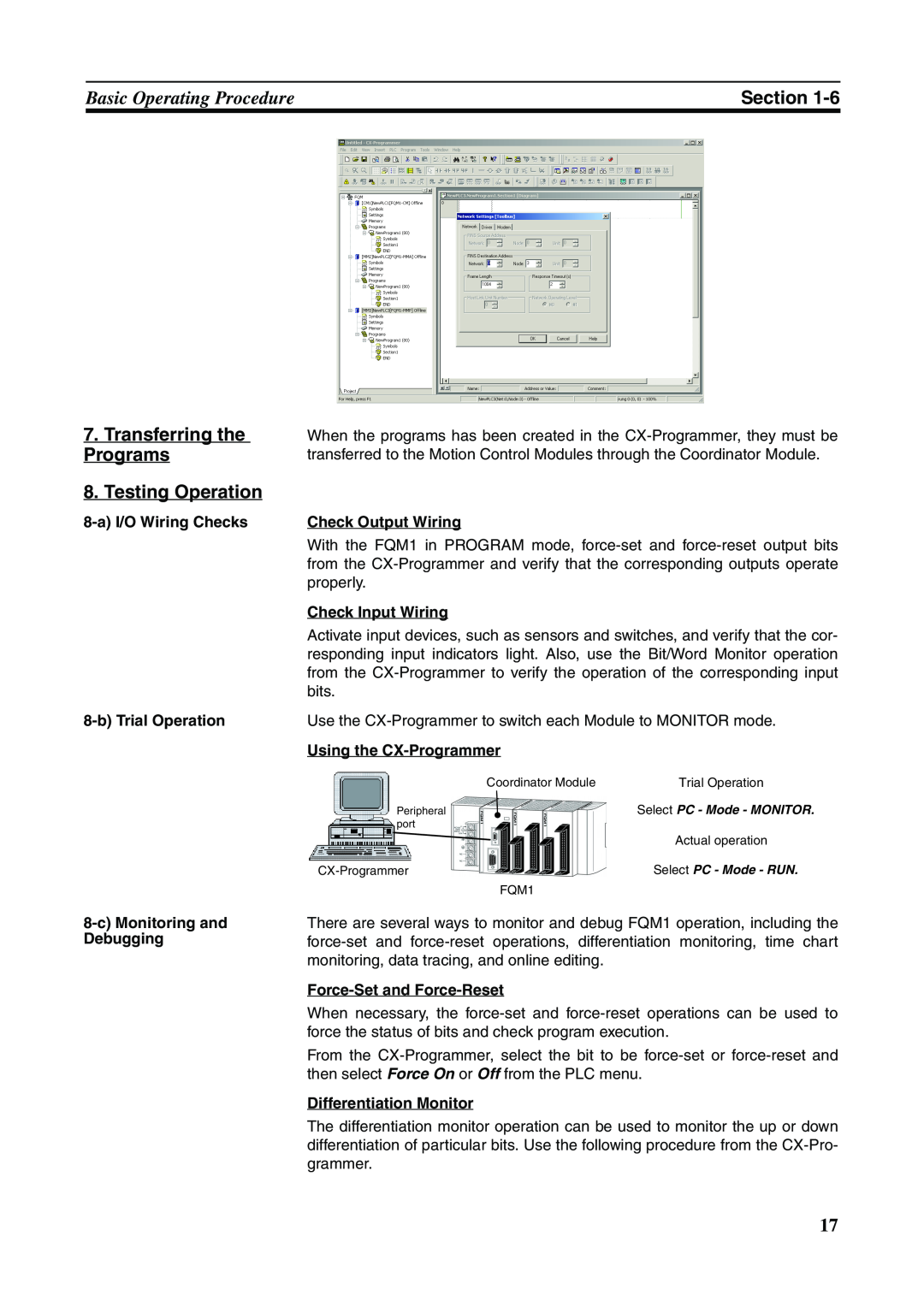
7.Transferring the Programs 8.Testing Operation
8-aI/O Wiring Checks 8-bTrial Operation
Check Output Wiring
Basic Operating Procedure
Time Chart Monitoring
Section
9.Save and Print the Programs
Function Tables Arranged by Purpose
5-4-4Settings
1-7-1
Sync Cycles and Synchronized data
Function Tables Arranged by Purpose
Section
5-1Synchronous Operation between Modules
5-1Synchronous Operation between Modules
1-7-2
Function Tables Arranged by PurposeSection
7-6-6Pulse Output Function Details
7-6-12PLS2887 Pulse Output Direction Prior
Function Tables Arranged by Purpose
Section
Absolute Encoders
7-6-6Pulse Output Function Details
Function Tables Arranged by Purpose
Section
7-10Analog Outputs
7-8Virtual Pulse Output Function
7-6-13Pulse Output Function Procedures
7-6-13Pulse Output Function Procedures
Function Tables Arranged by Purpose
Section
1-7-3
Function Tables Arranged by Purpose
Section
7-9Analog Input Functions
7-9-3Analog Input Function Specifications
1-7-4
Function Tables Arranged by Purpose
Section
Function Tables Arranged by Purpose
Section
7-9Analog Input Functions
7-6Pulse Outputs
7-4Interval Timer Interrupts
7-4-3Interval Timer Interrupt Modes
7-4Interval Timer Interrupts
7-4-3Interval Timer Interrupt Modes
Function Tables Arranged by Purpose
Section
7-5Pulse Inputs
7-6-8Time Measurement with the Pulse
Function Tables Arranged by Purpose
Section
SECTION Specifications and Nomenclature
General Specifications
List of Models
General Specifications
List of ModelsSection
Power Supply Unit Specifications
General Specifications
Section
2-3Coordinator Module
Indicators
Coordinator Module
Section
Function Specifications
Switch on Front Panel
Coordinator Module
Section
Section
Coordinator Module
CIO Area
Motion Control Modules
I/O Specifications
Motion Control Modules
Section
Indicators
Motion Control Modules
Section
Nomenclature
Motion Control Modules
Performance Specifications
Section
I/O Specifications
General-purposeI/O Specifications
Motion Control Modules
Section
Pulse I/O Specifications
Motion Control Modules
Section
FQM1-MMP21Pulse I/O
I/O Specifications
Motion Control Modules
Section
Pulse Inputs and Analog
2-5Dimensions
Dimensions
Section
FQM1-CM001Coordinator Module
Dimensions
Power Supply Units
POWER L1
POWER L1
2-6Module Current Consumption
Maximum Current and Maximum Total Power
Module Current Consumption
Section
Example Calculation of Current and Power
Combining Power Supply Units and Motion Control
Module Current Consumption
Section
2-7Memory Block Diagram
Memory Block Diagram
Section
Areas Backed Up by Super Capacitors
Memory Block Diagram
Section
SECTION Installation and Wiring
3-1Installation
Installation
Installation in Cabinets or Control Panels
Temperature Control
Installation
Power lines 200 mm min FQM1 200 mm min
Section
Improving Noise Resistance
Section
Installation
FQM1 Orientation
3-1-2Installation in a Control Panel
Installation
Wiring Ducts
Wiring Duct Example
3-1-3Assembled Appearance and Dimensions
Installation
Routing Wiring Ducts
Section
Installation
Assembled Dimensions
Installation Dimensions
Power Supply Unit width: “a” mm
3-1-4Connecting FQM1 Components
Installation
Installation Height
Section
3-1-5DIN Track Installation
Installation
Release DIN Track mounting pins
Section
2 3. Lock the pins on the backs of the Modules
Installation
Section
Installation
DIN Track and Accessories
Section
•DIN Track
3-2Wiring
Wiring
AC Power Source
Power Supply Capacity
Wiring
Section
Grounding
Terminal Screws and
Wiring
Section
FQM1
Control panel
Wiring
Crimp Terminals for Ground Wire
Section
Terminal Screws and
WiringSection
Connector Pin Arrangement
Connection Methods
1:1 Connections with
Wiring
Applicable Connectors
Coordinator Module Connector
IBM PC/AT or Compatible Connector 9-pin,Male
Wiring
RS-232CPort Specifications
Section
Connection Example to Programmable Terminal PT
3-3Wiring Module Connectors
Wiring Module Connectors
General-purposeI/O 40-pinConnector
Section
Wiring Module Connectors
General-purposeI/O 26-pinConnector
FQM1-MMP21Pulse I/O 40-pinConnector
Section
FQM1-MMA21Analog I/O 40-pinConnector
Wiring Module Connectors
Section
Wiring Module Connectors
3-3-2
Section
FQM1-MM@21Motion Control Modules
3-3-3Wiring Examples
Wiring Module Connectors
Connecting Pulse Inputs FQM1-MMP21 MMA21
Section
Wiring Module Connectors
Power supply Encoder
Section
FQM1 Shielded twisted-paircable
Wiring Module Connectors
Connecting Pulse Outputs FQM1-MMP21
Section
Example
Wiring Module Connectors
Connecting Analog Outputs FQM1 MMA21
Connecting Analog Inputs FQM1-MMA21
Connectors
3-4Wiring Servo Relay Units
Wiring Servo Relay Units
Recommended Wire Size
Section
Section
Wiring Servo Relay Units
Nomenclature and Functions
Wiring Servo Relay Units
Section
Upper Terminal Block Pin Arrangement
Lower Terminal Block Pin Arrangement
6. Signal Switches
Wiring Servo Relay Units
Section
Wiring Servo Relay Units
External Dimensions
Wiring Screw-less Clamp Terminal Blocks
Wiring Method
Wiring Servo Relay Units
Section
Recommended Screwdriver
Model
Wiring when Using Servo Relay Units
Wiring Servo Relay Units
Section
Wiring Servo Relay Units
Example Servo Relay Unit Wiring
Section
Upper Terminal Block Arrangement
3-5List of FQM1 Connecting Cables
List of FQM1 Connecting Cables
Connecting Cable Models
Section
6.Servomotor Connecting Cables
List of FQM1 Connecting Cables
Section
3-6Wiring Precautions
Wiring Precautions
I/O Signal Wiring
3-6-1Reducing Electrical Noise
Wiring Precautions
External Wiring
Surge suppressor specifications
Diode specifications
3-6-2Connecting I/O Devices
Wiring Precautions
Section
Input Devices
Wiring Precautions
Precautions when Connecting a Two-wireDC Sensor
Section
1,2,3
Wiring Precautions
Output Wiring Precautions
Section
Output Short-circuitProtection
Wiring Precautions
Section
FQM1
FQM1
SECTION Operation
4-1Coordinator Module
Coordinator Module
Section
User Program
System Setup Flash Memory
4-1-2Coordinator Module Operation
Coordinator Module
Section
4-1-3I/O Refreshing and Peripheral Servicing
4-1-4Startup Initialization
Coordinator Module
Section
4-2Motion Control Modules
4-2-1Outline
4-2-2Description of Each Area
Motion Control Modules
I/O Memory System Setup
System Setup Using CX-Programmer
Motion Control Modules
Section
Section
Motion Control Modules
Sync Mode Operation
Initialization at At power ON Common Processing
Motion Control Modules
Section
Program Execution
4-3Operating Modes
4-3-2
Status and Operations in Each Operating Mode
Operating Modes
4-4Power OFF Operation
4-4-1Power OFF Operation
Power OFF OperationSection
4-3-3Operating Mode Changes and I/O Memory
Power OFF Operation
Power OFF Timing Chart
Fixed Power OFF Detection Time
User-setPower OFF Detection Time
Section
Power OFF Operation
Description of Operation
SECTION Module Functions and Data Exchange
Synchronous Operation between Modules
Synchronous Operation between ModulesSection
Sync and ASync Modes
Sync Mode
Data Exchange between Modules
5-2Data Exchange between Modules
Section
5-3Cyclic Refresh
5-3-1Outline
5-3-2Applications
Cyclic Refresh
5-3-3Cyclic Refresh Area Details
Cyclic Refresh
Section
Coordinator Module Cyclic Refresh Area
Cyclic Refresh Area Allocations
5-3-4
Cyclic Refresh
Section
Synchronous Data Refresh
5-4-1
Outline
5-4-2
Synchronous Data Link Bit Area
5-4-3
Synchronous Data Refresh
Section
System Setup Coordinator Module
Synchronous Data Refresh
Section
Synchronization between Modules
5-5DM Data Transfer
System Setup Motion Control Modules
DM Data Transfer
Section
Settings Details
Step 1: Make Auxiliary Area Settings
5-5-3Executing DM Data Transfer
5-5-2
5-6Cycle Time Settings
Cycle Time Settings
5-6-1Constant Cycle Time Function
Section
Cycle Time Settings
System Setup
Constant Cycle Time Exceeded Error Clear Bit
Section
Cycle Time Settings
System Setup
Section
Cycle Time Too Long Flag
Cycle Time Settings
Constant Cycle Time Exceeded Error Clear Function
Section
Normal Operation
Read Protection Using Passwords
System Setup
5-7-1Specifying the Startup Mode
5-7-2Program Protection
Automatic Backup to Flash Memory
Password Protection
5-7-3Flash Memory
Section
5-8Diagnostic Functions
Diagnostic Functions
Refer to SECTION 9 Error Processing for details
Section
5-8-2Failure Alarm Functions
Diagnostic Functions
Section
Operation of FAL006
Diagnostic Functions
Section
Operation of FALS007
FALS
SECTION Coordinator Module Functions
Serial Communications
Serial CommunicationsSection
Serial Communications
Section
Procedure
Host Link Communications
6-1-1
Serial CommunicationsSection
Host Link Commands
Section
Serial Communications
Link Units System Manual W143 for details
Serial Communications
FINS Commands
Section
Serial Communications
6-1-2 No-protocolCommunications RS-232CPort
Section
Procedure
End code setting
Serial Communications
Section
System Setup
RS-232CSettings Host Link Port Settings
System Setup
Serial Communications
System Configuration
6-1-4Serial PLC Links
Serial CommunicationsSection
Overview
Procedure
CJ1M Master Settings
FQM1 Slave Settings
Serial Communications
Settings
CJ1M Master PLC Setup
FQM1 Slave System Setup
System Configuration
System Setup
Smart Active Parts Communications Settings
Serial Communications
Section
RS-422ASettings
6-1-6 No-protocolCommunications RS-422APort
Serial Communications
Section
SECTION Motion Control Module Functions
7-6-10
Overview
OverviewSection
7-2Interrupt Functions
Interval Timer Interrupts
Interrupt Functions
Section
7-2-3Disabling and Enabling All Interrupts
Interrupt Functions
Section
Disabling All Interrupts
Input Interrupts
Input Interrupts
Section
Clearing Recorded Interrupts
7-3-5Using Input Interrupts
Input Interrupt Mode Procedure
Input Interrupts
Section
Counter Mode Procedure
Input Interrupts
Section
1,2,3
Input Interrupts
7-3-6Application Example
Section
7-4Interval Timer Interrupts
Interval Timer Interrupt Modes
7-4-4Using Interval Timer Interrupts
Interval Timer Interrupts
7-4-5Application Example
Interval Timer Interrupts
Section
Pulse Inputs
Specifications
7-5-1
Applicable Models
Pulse Inputs
Section
7-5-4Pulse Input Specifications
Pulse InputsSection
Pulse Inputs
Section
Minimum response pulse
At 50 kHz
Phases A and B
Phase Z
7-5-6
7-5-7
Input Signal Type and Count Mode
Phase Differential Inputs
Phase Differential Input Operation
Pulse Inputs
Reset Methods
Pulse Inputs
Section
Counter Operation Numeric Ranges
Phase-ZSignal Reset Input and Software Reset
Software Reset
Pulse Inputs
Section
Section
Pulse Inputs
Range Comparison Method
Section
Pulse Inputs
Monitoring High-speedCounter Movement Mode
High-speedCounter Movement Mode 1 Specifications
Pulse Inputs
Section
Monitoring a High-speedCounter’s Frequency Mode
Frequency Measurement Mode 2 Specifications
Pulse Inputs
Section
Latching a High-speedCounter’s PV
7-5-9Pulse Input Function Procedures
High-speedCounter Procedure
Pulse Inputs
Section
Pulse Inputs
Mode 1 Procedure
Section
Mode 2 Procedure
Procedure
Procedure
Pulse Inputs
Pulse Inputs
Section
Example
High-speed Counter PV
Pulse Inputs
Section
Example High-speedCounter Range Comparison
Bit Pattern Output
Section
Pulse Inputs
P_On
Section
Pulse Inputs
Example Latching High-speed Counter PV
Pulse Outputs
7-6-1
7-6-2
Pulse OutputsSection
Pulse OutputsSection
7-6-3
Acceleration/ decelera
Pulse Output Specifications
7-6-4
Pulse Outputs
Section
7-6-5
Applicable Instructions
Pulse OutputsSection
Instructions Ineffective during Pulse Output
7-6-6
Pulse Output Function Details
Pulse OutputsSection
Overview
Pulse Outputs
Section
Pulse output
Description
Procedure
Settings
Pulse Outputs
Section
Section
Pulse Outputs
Indepen
Precautions when Using Pulse Outputs
Pulse Outputs
Section
Target frequency
7-6-7 One-shotPulse Output Function
Pulse Outputs
Section
Formula
Pulse Outputs
One-shotPulse Output Specifications
Section
Pulse Outputs
7-6-8Time Measurement with the Pulse Counter
Section
Pulse Outputs
Pulse Counter Timer Specifications
Section
Pulse Outputs
Section
Linear Mode Operation
Frequency speed Target value Target value
Section
Pulse Outputs
3.00
Section
Circular Mode Operation
Single-rotationspeed control pattern
High-speedregion Low-speed 0region
Setting the
Pulse Outputs
Section
Speed-changeCycle
Setting the Pulse Output Direction Priority Mode
Pulse Outputs
Section
Pulse Output Direction Priority Mode
Section
Pulse Outputs
Pulse Outputs with Acceleration/Deceleration
Procedure
Pulse Outputs
Section
Electronic Cam Control Functions
Pulse Outputs
Section
Pulse Counter Timer Function STIM980
Pulse Outputs
Section
One-shotPulse Output STIM980
Pulse Outputs
7-6-14Pulse Output Function Examples
Section
Pulse Outputs
Section
Changing the Frequency in Steps
Accelerating the Frequency at a Fixed Rate
Pulse Outputs
Section
Specified number of pulses
Speed reaches 0 while the remaining
Section
Pulse Outputs
P_On Always ON Flag P_On Always ON Flag
Pulse Outputs
Section
Pulse Counter Time Measurement Timer Example
7-6-15Pulse Output Starting Conditions
Pulse Outputs
Section
Pulse Outputs
Section
Pulse Outputs
Section
PULS886 Absolute Pulse Output in Progress
Pulse Output Operation
Pulse Outputs
Section
PLS2887
Cases 1, 2, and
Pulse Outputs
Section
Cases 6, 8, 9, and
Cases 7, 11, 12,
7-7-2Overview
7-7-1Applicable Models
Section
Serial Data Specification
7-7-3Data Format of Absolute Encoder Output
Section
Data Format
7-7-4Counter Operation
Section
Counting Operation Counter Operation Details
Absolute Linear CW−
Section
7-7-6Absolute Present Value
Absolute Linear Counter Absolute Circular Counter
7-7-8Absolute Offset Preset
7-7-7Absolute Present Value Preset
Section
Related Areas
System Setup
7-7-9
Section
Auxiliary Area
A606
Section
Note Refer to 7-7-6Absolute Present Value
Step 1 Required: Setting
Setting the Pulse Input Method
Setting the Input Pulse Counting Speed
Setting the Counter Operation
Offset Preset
Step 4 Required Absolute Present Value Preset
Section
Step 3 as Needed: Origin Compensation Absolute
Section
Program Description
Section
0.00
Section
000005
7-8Virtual Pulse Output Function
7-8-1
7-8-2
Virtual Pulse Output FunctionSection
T First Word of Setting Table
Virtual Pulse Output FunctionSection
Overview
Operands
Section
Virtual Pulse Output Function
Description
7-9Analog Input Functions
Positioning or Speed Control Using a Virtual Axis
7-9-1
7-9-2
Analog Input Functions
Sensor pressure, displacement, etc
Section
7-9-3
Analog Input Function Specifications
Analog Input FunctionsSection
Related Areas and Settings
System Setup
Settings
Time when setting
Analog Input Functions
Section
Auxiliary Area
A550
Section
Analog Input Functions
A562
Section
Analog Input Functions
A570
Signal Range: −10 to 10 Signal Range: 0 to 10
7-9-5Applicable Instructions
7-9-6A/D Conversion Value
Analog Input Functions
Signal Range: 1 to 5 V and 4 to 20 mA
Signal Range: 0 to 5
Analog Input Functions
Section
Analog Input Functions
Section
Example
Application Example
7-10
Analog Outputs
7-10-1
7-10-2
7-10-3Analog Output Function Specifications
Analog OutputsSection
Analog Outputs
put Tab Page − Output
Section
Analog Outputs
CPU standby status
Specified Output Values and Analog Output Signals
Analog Outputs
Section
END Refreshing With Immediate Refreshing
Analog Outputs
7-10-5Procedure
Section
Analog Outputs
Section
Outputting the Analog Output Value Stored
in the Auxiliary Area
Analog Outputs
Section
Analog Outputs
Section
SECTION Connecting the CX-Programmer
CX-Programmer
CX-ProgrammerSection
8-2Connecting the CX-Programmer
Connecting the CX-Programmer
Connecting to the Peripheral Port
Connecting to the RS-232CPort
Connecting the CX-Programmer
Connecting to the Peripheral Port
Connection Diagram
Section
Connecting the CX-Programmer
Connecting to the RS-232CPort
Using an RS-232CCable
Section
Connecting the CX-Programmer
8-2-2 CX-ProgrammerConnecting Cables
Section
Connecting an RS-232CCable to the RS-232CPort
Connecting the CX-Programmer
Section
Connecting the CX-Programmer
Section
SECTION Error Processing
9-1Error Log
Error Log
Errors Generated by FAL006/FALS007
Error Log Structure
Error Processing
Error Categories
9-2-2Error Information
Error ProcessingSection
Error Codes
Error Processing
9-2-3
Section
Error Processing
9-2-4Error Processing Flowchart
Section
Error Processing
CPU Errors
Fatal Errors
Section
message and related Auxiliary Area flags/words and correct the cause of the error
Error Processing
Section
Error Processing
Fatal Errors
Error
Error
Error Processing
Non-fatalErrors
Non-fatalErrors
Section
Other Errors
Error Processing
Section
Error Processing
9-2-6Power Supply Check
Section
9-2-7Memory Error Check
9-2-8Program Error Check
Error Processing
Section
9-2-9Cycle Time Overrun Error Check
9-2-10System Setup Error Check
Error Processing
Section
9-2-11I/O Setting Error Check
Error Processing
I/O Setting Error occurred
Section
9-2-12I/O Check
Error Processing
Section
Troubleshooting Problems in Modules
Troubleshooting Problems in Modules
Coordinator Module Errors
9-2-13Environmental Conditions Check
Troubleshooting Problems in Modules
Motion Control Module Errors
Input Errors
Section
Output Errors
Troubleshooting Problems in Modules
Section
Inspection and Maintenance
SECTION
Module Replacement Precautions
10-1Inspections
10-1Inspections
10-1-1Inspection Points
InspectionsSection
Inspection Points for Periodic Inspections
Inspections
Section
Tools Required for Inspections
Required Tools
Inspections
Section
Appendix A
Programming Programs and Tasks
Subroutines
Using Normal Subroutines
What Are Subroutines?
Programming
Using Subroutines That Pass Parameters
Programming
Appendix A
Execution with Subroutine Input Condition Flags
Programming
Appendix A
JSB982 Operation
Address
Programming
Appendix A
Application Examples
Without Macro Function
Programming
Appendix A
Execution with Subroutine Input Condition Flags
Main Program
Basic Information on Programming
Power Flow
Programming
Appendix A
Programming
Appendix A
Flags
Operands
Instruction Location and Input Conditions
Addressing I/O Memory Areas
Programming
Appendix A
Specifying Operands
Programming
Appendix A
Operand
Programming
Appendix A
Operand
Description
Appendix A
Programming
Operand
Programming
Appendix A
Upper 4 bits
Lower 4 bits
Data Formats
Programming
Appendix A
Note Signed Binary Data
Programming
Appendix A
Complements
Two’s Complements
ProgrammingAppendix A
Note Signed BCD Data
Instruction Variations
Input Conditions
Programming
Appendix A
Appendix A
Programming
Upwardly differentiated input instruction
Programming Precautions
Using Condition Flags
Condition Flags
Programming
1.Using Execution Results in NC and NO Inputs
Programming
Appendix A
Instruction A
Programming
Appendix A
CMP 0010 D00100 Reflects CMP execution results
MOV 1 0200 D00200 Reflects MOV execution results
Error Flag
Programming
Appendix A
Main Conditions Turning ON Condition Flags
Programming
Appendix A
Equals Flag
Carry Flag
Special Program Sections
Programming
Appendix A
Instruction Combinations
Programming
Appendix A
Instructions Not Allowed in Subroutines
Note Block Program Sections
Computing the Cycle Time
FQM1 Operation Flowchart
Programming
Appendix A
Overview of Cycle Time Calculations
Programming
Appendix A
Coordinator Module
Programming
Appendix A
Module I/O Refresh Times
Programming
Appendix A
Cyclic Refresh Time in the Coordinator Module
Example of Calculating the Cycle Time
Online Editing Cycle Time Extension
Programming
Appendix A
Response Time
Programming
Appendix A
Coordinator Module I/O Response Time
Programming
Appendix A
Motion Control Module I/O Response Time
Minimum I/O Response Time General-purposeI/O 0 to
Programming
Appendix A
Motion Control Module Interrupt Response Times
Calculation Example
Programming
Appendix A
Motion Control Module Interrupt Processing Times
Scheduled Interrupt Task
Programming
Appendix A
Processing Time
Interrupt Response Time Calculation Example
Programming
2When using interrupt tasks frequently, be sure to consider the time required for interrupt processing and its affect on the overall system
Appendix A
Appendix B
I/O Memory Overview of I/O Memory
I/O Memory
Parameter Area
I/O Memory Structure
Coordinator Module
I/O Memory
Appendix B
I/O Memory
Motion Control Modules
Appendix B
CIO Area
I/O Memory
Appendix B
I/O Bit Area: CIO 0000 and CIO
I/O Memory
Appendix B
Synchronous Data Link Bit Area: CIO 0200 to
Serial PLC Link Bit Area CIO 0080 to CIO
Auxiliary Area: A000 to A649 A000.00 to A649.15
Temporary Relay Area TR
Refreshing Using the IORF097 Instruction
I/O Memory
I/O Memory
Timer Area
Appendix B
I/O Memory
Counter Area
Appendix B
Data Memory DM Area
Condition Flags
Binary-modeAddressing @D
BCD-modeAddressing *D
Using the Condition Flags
symbol
I/O Memory
Appendix B
Clock Pulses
Using the Clock Pulses
I/O Memory
Appendix B
Parameter Area
System Setup
I/O Memory
Appendix B
System Setup, Auxiliary Area Allocations
Overview of System Setups
System Setup in the Coordinator Module
Appendix C
Appendix C
Peripheral Port Settings for Host Link
Communications Settings
Standard/Custom Setting
Appendix C
Peripheral Port Settings for NT Link
Standard/Customer Setting
Appendix C
Host Link Unit Number
RS-232CPort Settings for Host Link
Appendix C
Baud Rate
Serial Communications Mode
RS-232CPort Settings for NT Link
RS-232CPort Settings for Peripheral Bus ToolBus
Standard/Custom Setting
Appendix C
Send Delay
Appendix C
Baud Rate
Serial Communications Mode
RS-232CPort Settings for PLC Link PC Link Slave
Appendix C
Start Code and End Code
Number of Received Bytes
RS-422APort Settings CX-Programmer:Drive Tab Page
RS-422APort Settings for Serial Gateway
Standard/Custom Setting
Send Delay Time
Peripheral Service Time
Appendix C
Start Code and End Code
Number of Received Bytes
System Setup in Motion Control Modules
CX-Programmer:Module Settings Tab Page
Appendix C
CX-Programmer:Cycle Time Tab Page
FQM1-MMP21Motion Control Modules with Pulse I/O
CX-Programmer:Pulse Input Tab Page
Appendix C
CX-Programmer:Pulse Output Tab Page
Pulse Output
Function Details
When setting
FQM1-MMA21Motion Control Modules with Analog I/O
Appendix C
CX-Programmer:Pulse Input Tab Page
Details on System Setup Settings
Peripheral Port Settings
RS-232CPort Settings Host Link Port
Appendix C
Appendix C
Constant Cycle Time
Watch Cycle Time
Messages Sent and Received with No-protocolMode
Appendix C
Fixed Peripheral Servicing Time
The default value for each servicing process is 6.25% of the last cycle’s cycle time. In general, it is rec- ommended that the default value be used. Set a uniform servicing time only when peripheral servicing is being delayed because each service process is being spread over several cycles
Appendix C
Auxiliary Area Allocations by Function
Appendix C
Allocations That Are the Same for All Modules
FQM1-MMP21Motion Control Modules with Pulse I/O
Appendix C
A608
Appendix C
Address
Bits
Name
Appendix C
A610
Appendix C
A611
Appendix C
A620 to
Appendix C
A626
Appendix C
FQM1-MMA21Motion Control Modules with Analog I/O
Address
Bits
Appendix C
A562
Appendix C
A564
flows/underflows are checked when the PV is read
Appendix C
Note For a Linear Counter, high-speedcounter over
change in the PV of the high-speedcounter over
Appendix C
Address
Bits
Name
Appendix C
Address
Bits
Name
Appendix C
A610
Appendix C
Allocations Related to Built-inInputs
Input Interrupts
Program Error Flags
Other Error Flags and Bits
Error Log and Error Code
Appendix C
FAL/FALS Errors
Memory Errors
System Setup
I/O Errors
Appendix C
Communications
Other
Peripheral Port
Built-inI/O Allocations
Allocations Directly Related to Instructions
Appendix C
RS-232CPort
Inputs 40-pin General-purposeI/O Connector
Outputs 40-pin General-purposeI/O Connector
Inputs 26-pin General-purposeI/O Connector
Outputs 26-pin General-purposeI/O Connector
Auxiliary Area Allocations
Appendix D
Auxiliary Area Allocations in Order of Address
Auxiliary Area Allocations
Appendix D
Appendix D
Auxiliary Area Allocations
A414
Appendix D
Auxiliary Area Allocations
A520
Appendix D
Auxiliary Area Allocations
A559
Appendix D
Auxiliary Area Allocations
A570
Appendix D
Auxiliary Area Allocations
A606 to
Appendix D
Auxiliary Area Allocations
A610
Appendix D
Auxiliary Area Allocations
A612
Appendix D
Auxiliary Area Allocations
A626
Error Codes and Error Flags
Error Log Area: A100 to A199
Detailed Explanations on the Auxiliary Area
Auxiliary Area Allocations
Memory Configuration
FQM1 Memory Addresses
Auxiliary Area Allocations
Appendix D
Memory Map
Auxiliary Area AllocationsAppendix D
Auxiliary Area Allocations
Appendix D
Sequence Input Instructions
Sequence Output Instructions
Timer and Counter Instructions
Auxiliary Area Allocations
Appendix D
Sequence Control Instructions
Appendix D
Auxiliary Area Allocations
Data Movement Instructions
Auxiliary Area Allocations
Appendix D
Data Shift Instructions
Increment/Decrement Instructions
Auxiliary Area Allocations
Symbol Math Instructions
Appendix D
Auxiliary Area Allocations
Appendix D
Conversion Instructions
Logic Instructions
Auxiliary Area Allocations
Appendix D
Special Math Instructions
Floating-pointMath Instructions
Auxiliary Area Allocations
Appendix D
Table Data Processing Instructions
Data Control Instructions
Auxiliary Area Allocations
Appendix D
Interrupt Control Instructions
High-speedCounter and Pulse Output Instructions
Auxiliary Area Allocations
Appendix D
Step Instructions
I/O Refresh Instruction
Auxiliary Area Allocations
Appendix D
Serial Communications Instructions
Debugging Instructions
Appendix D
Auxiliary Area Allocations
Branching
Auxiliary Area Allocations
Appendix D
Index
Index
Index
Index
Index
Page
Index
Index
Peripheral Devices, 6 peripheral port
Index
Index
Servo Drivers
Index
Index
Revision History
Cat. No. O010-E1-01
Page
OMRON CORPORATION
FA Systems Division H.Q 66 Matsumoto
Mishima-city,Shizuoka Japan
Tel: 8155-977-9181/Fax:
Certain Precautions on Specifications and Use
Terms and Conditions of Sale
OMRON ELECTRONICS LLC
1 Commerce Drive Schaumburg, IL
OMRON CANADA, INC
885 Milner Avenue Toronto, Ontario M1B