F201 | F201 |
/I | V/I Input Point 1 Setting |
| Program ⇒ Frequency ⇒ Speed Reference Setpoints |
| This parameter is used to set the gain and bias of the isolated V/I input terminal |
| when the V/I terminal is used as the control input while operating in the Speed |
| Control mode or the Torque Control mode. |
| This parameter sets the V/I input level that is associated with the V/I Input |
| Point 1 Frequency setting when operating in the Speed control mode or is |
| associated with the V/I Input Point 1 Rate setting when operating in the |
| Torque Control mode. |
| Note: See note on pg. 44 for more information on the V/I terminal. |
Direct Access Number — F201
Parameter Type — Numerical
Factory Default — 0
Changeable During Run — Yes
Minimum — 0
Maximum — 100
Units — %
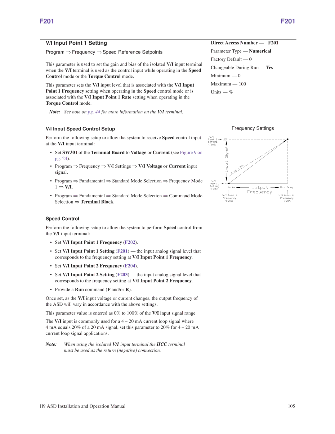
V/I Input Speed Control Setup | Frequency Settings |
Perform the following setup to allow the system to receive Speed control input at the V/I input terminal:
• Set SW301 of the Terminal Board to Voltage or Current (see Figure 9 on pg. 24).
• Program ⇒ Frequency ⇒ V/I Settings ⇒ V/I Voltage or Current input signal.
• Program ⇒ Fundamental ⇒ Standard Mode Selection ⇒ Frequency Mode 1 ⇒ V/I.
• Program ⇒ Fundamental ⇒ Standard Mode Selection ⇒ Command Mode
Selection ⇒ Terminal Block.
Speed Control
Perform the following setup to allow the system to perform Speed control from the V/I input terminal:
•Set V/I Input Point 1 Frequency (F202).
•Set V/I Input Point 1 Setting (F201) — the input analog signal level that corresponds to the frequency setting at V/I Input Point 1 Frequency.
•Set V/I Input Point 2 Frequency (F204).
•Set V/I Input Point 2 Setting (F203) — the input analog signal level that corresponds to the frequency setting at V/I Input Point 2 Frequency.
•Provide a Run command (F and/or R).
Once set, as the V/I input voltage or current changes, the output frequency of the ASD will vary in accordance with the above settings.
This parameter value is entered as 0% to 100% of the V/I input signal range.
The V/I input is commonly used for a 4 – 20 mA current loop signal where
4 mA equals 20% of a 20 mA signal, set this parameter to 20% for 4 – 20 mA current loop signal applications.
Note: When using the isolated V/I input terminal the IICC terminal must be used as the return (negative) connection.
H9 ASD Installation and Operation Manual | 105 |
