F270 | F270 |
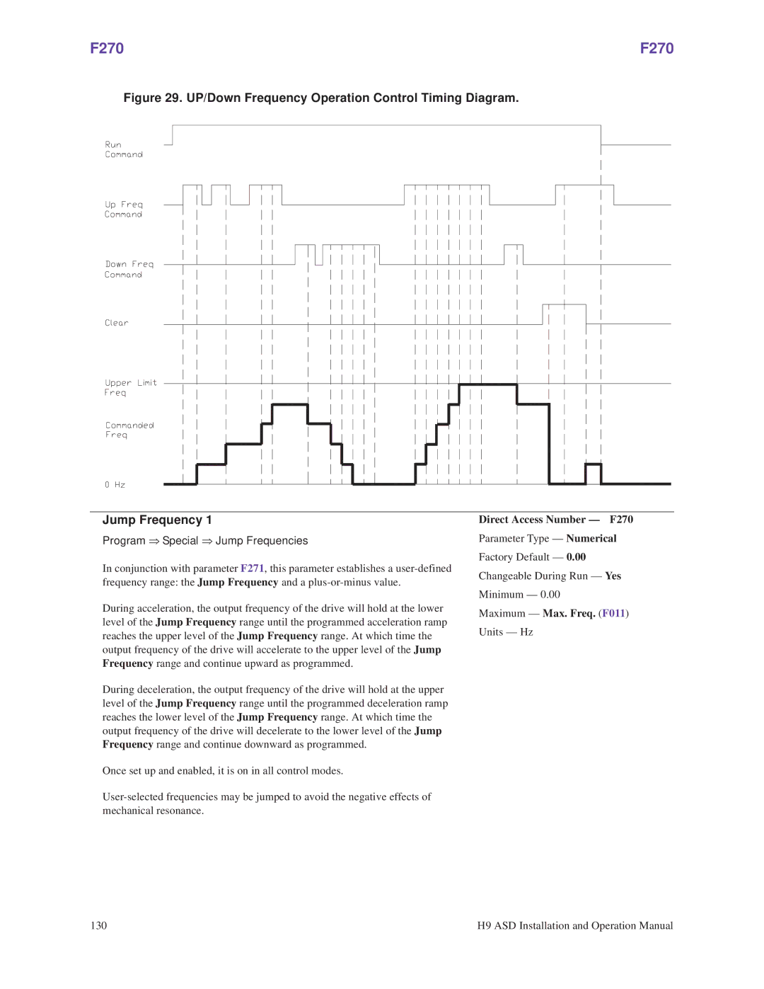
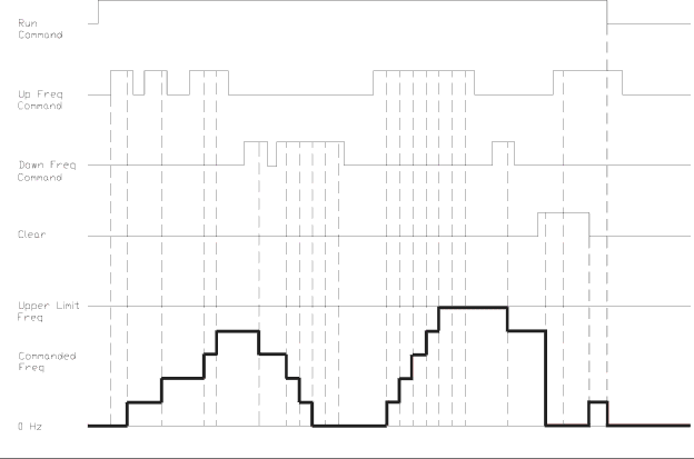
Figure 29. UP/Down Frequency Operation Control Timing Diagram.
Jump Frequency 1
Program ⇒ Special ⇒ Jump Frequencies
In conjunction with parameter F271, this parameter establishes a
During acceleration, the output frequency of the drive will hold at the lower level of the Jump Frequency range until the programmed acceleration ramp reaches the upper level of the Jump Frequency range. At which time the output frequency of the drive will accelerate to the upper level of the Jump Frequency range and continue upward as programmed.
During deceleration, the output frequency of the drive will hold at the upper level of the Jump Frequency range until the programmed deceleration ramp reaches the lower level of the Jump Frequency range. At which time the output frequency of the drive will decelerate to the lower level of the Jump Frequency range and continue downward as programmed.
Once set up and enabled, it is on in all control modes.
Direct Access Number — F270
Parameter Type — Numerical
Factory Default — 0.00
Changeable During Run — Yes
Minimum — 0.00
Maximum — Max. Freq. (F011)
Units — Hz
130 | H9 ASD Installation and Operation Manual |