LC
LB
LA
FLC — FLC is the common leg of a
FLB — The
FLA — The
Note: The FLA, FLB, and FLC contacts are rated at 2A/120 VAC and 2A/30 VDC.
Figure 8. FLA, FLB, and FLC switching contacts shown in the de-energized state.
Note: The relay is shown in the Faulted or
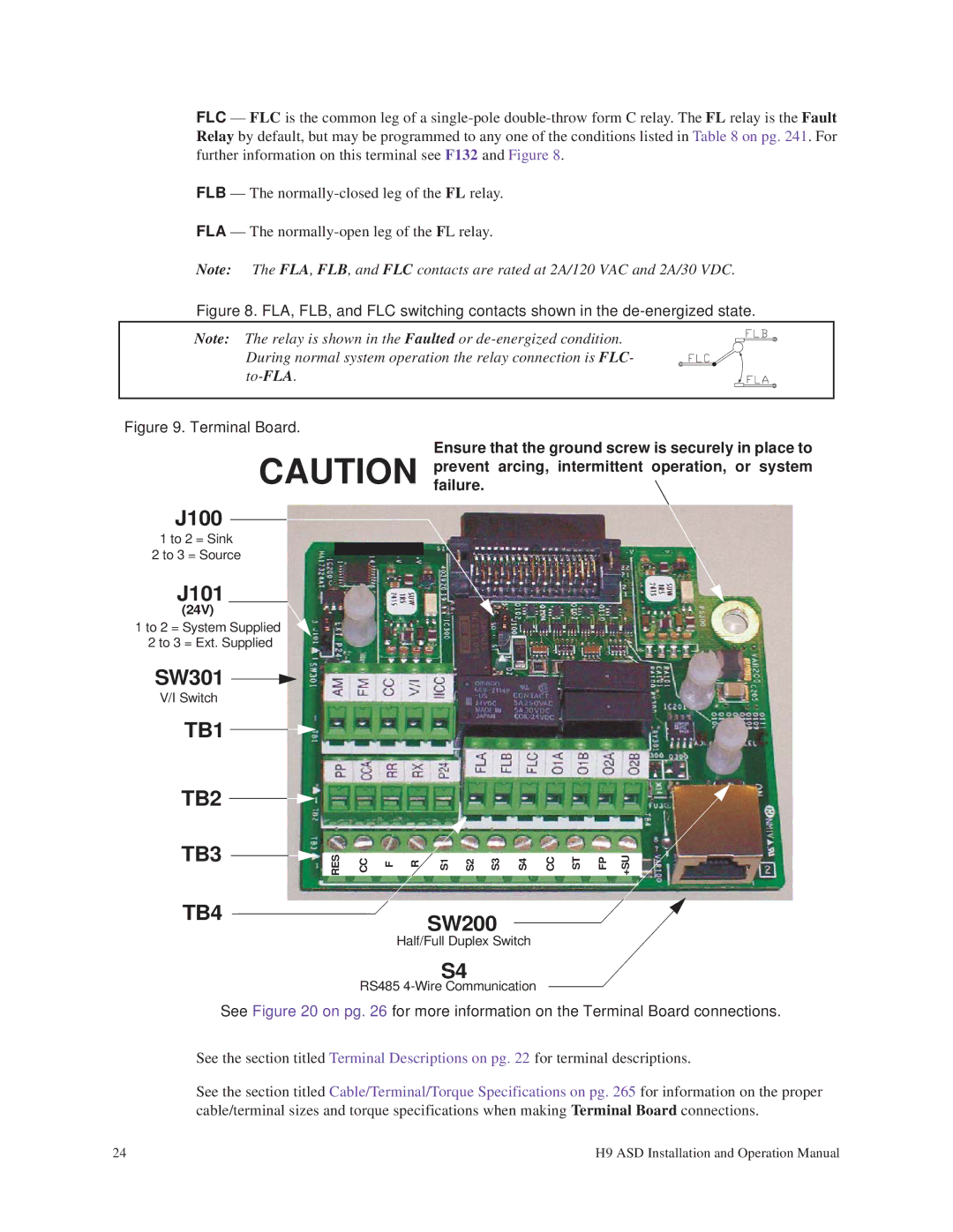
Figure 9. Terminal Board.
Ensure that the ground screw is securely in place to CAUTION preventfailure. arcing, intermittent operation, or system
J100
1 to 2 = Sink
2 to 3 = Source
J101
(24V)
1 to 2 = System Supplied
2 to 3 = Ext. Supplied
SW301 ![]()
![]()
V/I Switch
TB1
TB2 |
|
|
|
|
|
|
|
|
|
|
|
|
TB3 | RES | CC | F | R | S1 | S2 | S3 | S4 | CC | ST | FP | +SU |
|
TB4SW200
Half/Full Duplex Switch
S4
RS485
See Figure 20 on pg. 26 for more information on the Terminal Board connections.
See the section titled Terminal Descriptions on pg. 22 for terminal descriptions.
See the section titled Cable/Terminal/Torque Specifications on pg. 265 for information on the proper cable/terminal sizes and torque specifications when making Terminal Board connections.
24 | H9 ASD Installation and Operation Manual |