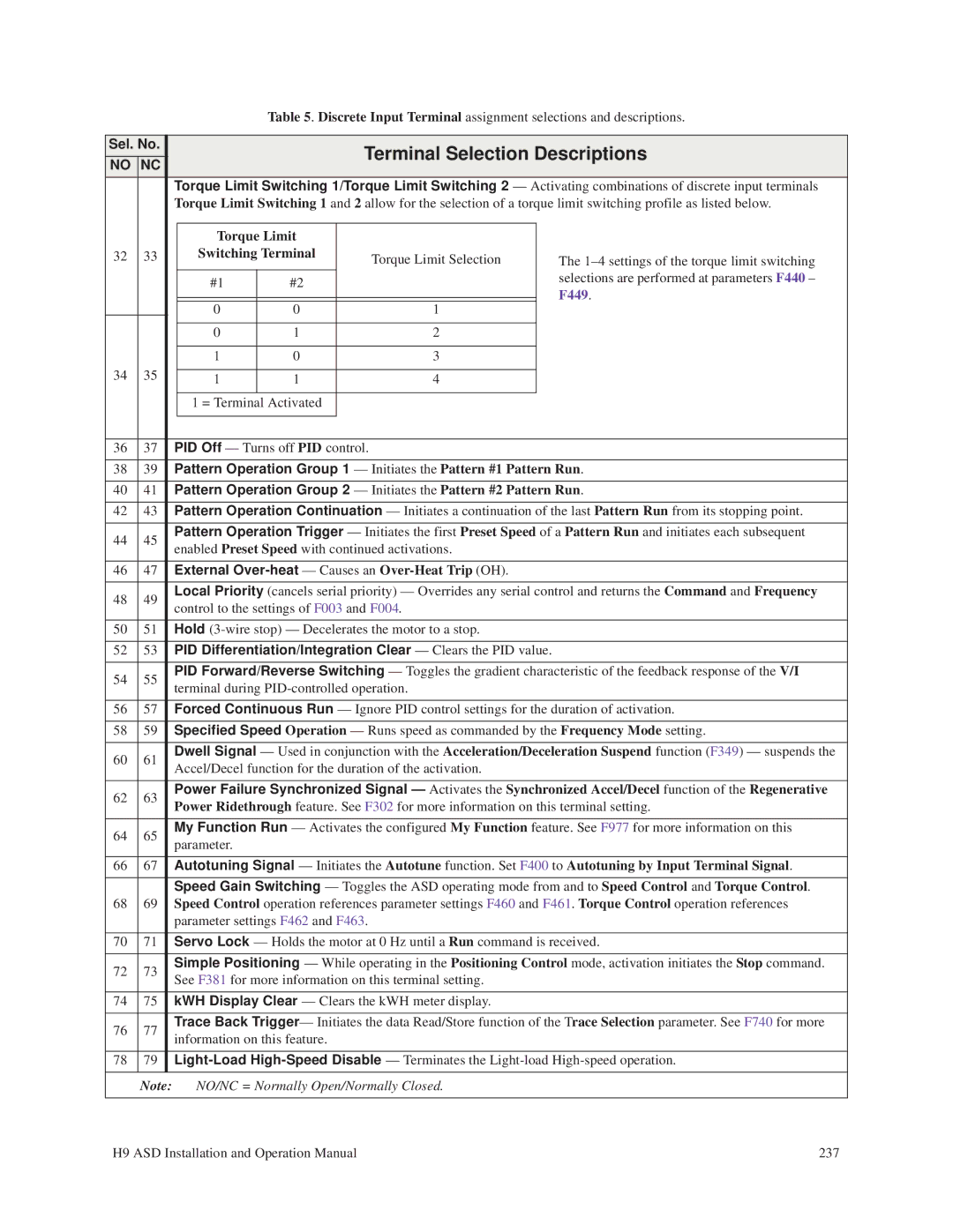
Table 5. Discrete Input Terminal assignment selections and descriptions.
Sel. No. |
|
|
|
| Terminal Selection Descriptions | ||||
NO | NC |
|
|
|
| ||||
|
|
|
|
|
|
|
| ||
|
|
| Torque Limit Switching 1/Torque Limit Switching 2 — Activating combinations of discrete input terminals | ||||||
|
|
| Torque Limit Switching 1 and 2 allow for the selection of a torque limit switching profile as listed below. | ||||||
|
|
|
|
|
|
|
|
|
|
|
|
|
| Torque Limit |
|
|
|
| |
32 | 33 |
|
| Switching Terminal |
| Torque Limit Selection |
| The | |
|
|
|
| #1 | #2 |
|
|
| selections are performed at parameters F440 – |
|
|
|
|
|
|
| F449. | ||
|
|
|
|
|
|
|
|
| |
|
|
|
|
|
|
|
|
| |
|
|
|
| 0 | 0 |
| 1 |
|
|
|
|
|
|
|
|
|
|
|
|
|
|
|
| 0 | 1 |
| 2 |
|
|
|
|
|
|
|
|
|
|
|
|
|
|
|
| 1 | 0 |
| 3 |
|
|
34 | 35 |
|
|
|
|
|
|
|
|
|
| 1 | 1 |
| 4 |
|
| ||
|
|
|
|
|
|
|
|
|
|
|
|
|
| 1 = Terminal Activated |
|
|
|
| |
|
|
|
|
|
|
|
|
|
|
|
|
|
|
|
|
|
|
|
|
36 | 37 |
| PID Off — Turns off PID control. |
|
|
| |||
|
|
|
|
|
|
|
| ||
38 | 39 |
| Pattern Operation Group 1 — Initiates the Pattern #1 Pattern Run. | ||||||
|
|
|
|
|
|
|
| ||
40 | 41 |
| Pattern Operation Group 2 — Initiates the Pattern #2 Pattern Run. | ||||||
|
|
|
|
|
|
|
| ||
42 | 43 |
| Pattern Operation Continuation — Initiates a continuation of the last Pattern Run from its stopping point. | ||||||
|
|
|
|
|
|
|
| ||
44 | 45 |
| Pattern Operation Trigger — Initiates the first Preset Speed of a Pattern Run and initiates each subsequent | ||||||
| enabled Preset Speed with continued activations. |
| |||||||
|
|
|
| ||||||
|
|
|
|
|
|
|
|
| |
46 | 47 |
| External |
| |||||
|
|
|
|
|
|
|
| ||
48 | 49 |
| Local Priority (cancels serial priority) — Overrides any serial control and returns the Command and Frequency | ||||||
| control to the settings of F003 and F004. |
| |||||||
|
|
|
| ||||||
|
|
|
|
|
|
|
|
| |
50 | 51 |
| Hold |
| |||||
|
|
|
|
|
|
|
|
| |
52 | 53 |
| PID Differentiation/Integration Clear — Clears the PID value. |
| |||||
|
|
|
|
|
|
|
| ||
54 | 55 |
| PID Forward/Reverse Switching — Toggles the gradient characteristic of the feedback response of the V/I | ||||||
| terminal during |
| |||||||
|
|
|
| ||||||
|
|
|
|
|
|
|
| ||
56 | 57 |
| Forced Continuous Run — Ignore PID control settings for the duration of activation. | ||||||
|
|
|
|
|
|
|
| ||
58 | 59 |
| Specified Speed Operation — Runs speed as commanded by the Frequency Mode setting. | ||||||
|
|
|
|
|
|
|
| ||
60 | 61 |
| Dwell Signal — Used in conjunction with the Acceleration/Deceleration Suspend function (F349) — suspends the | ||||||
| Accel/Decel function for the duration of the activation. |
| |||||||
|
|
|
| ||||||
|
|
|
|
|
|
|
| ||
62 | 63 |
| Power Failure Synchronized Signal — Activates the Synchronized Accel/Decel function of the Regenerative | ||||||
| Power Ridethrough feature. See F302 for more information on this terminal setting. | ||||||||
|
|
| |||||||
|
|
|
|
|
|
|
| ||
64 | 65 |
| My Function Run — Activates the configured My Function feature. See F977 for more information on this | ||||||
| parameter. |
|
|
|
|
| |||
|
|
|
|
|
|
|
| ||
|
|
|
|
|
|
|
| ||
66 | 67 |
| Autotuning Signal — Initiates the Autotune function. Set F400 to Autotuning by Input Terminal Signal. | ||||||
|
|
|
|
|
|
|
| ||
|
|
| Speed Gain Switching — Toggles the ASD operating mode from and to Speed Control and Torque Control. | ||||||
68 | 69 |
| Speed Control operation references parameter settings F460 and F461. Torque Control operation references | ||||||
|
|
| parameter settings F462 and F463. |
|
|
| |||
|
|
|
|
|
|
|
| ||
70 | 71 |
| Servo Lock — Holds the motor at 0 Hz until a Run command is received. | ||||||
|
|
|
|
|
|
|
| ||
72 | 73 |
| Simple Positioning — While operating in the Positioning Control mode, activation initiates the Stop command. | ||||||
| See F381 for more information on this terminal setting. |
| |||||||
|
|
|
| ||||||
|
|
|
|
|
|
|
|
| |
74 | 75 |
| kWH Display Clear — Clears the kWH meter display. |
| |||||
|
|
|
|
|
|
|
| ||
76 | 77 |
| Trace Back Trigger— Initiates the data Read/Store function of the Trace Selection parameter. See F740 for more | ||||||
| information on this feature. |
|
|
| |||||
|
|
|
|
|
| ||||
|
|
|
|
|
|
|
| ||
78 | 79 |
| |||||||
|
|
|
|
|
|
|
|
| |
| Note: |
| NO/NC = Normally Open/Normally Closed. |
| |||||
|
|
|
|
|
|
|
|
|
|
H9 ASD Installation and Operation Manual | 237 |