Manuals
/
Toshiba
/
Computer Equipment
/
Network Card
Toshiba
H9
operation manual
261
Models:
H9
1
269
289
289
Download
289 pages
12.38 Kb
266
267
268
269
270
271
272
273
Specifications
Motor Characteristics
Install
Typical Connection Diagram
Signal Words
Password
Changed From Default
Input Terminal Delays
Special Symbols
Connecting the H9 ASD
Page 269
Image 269
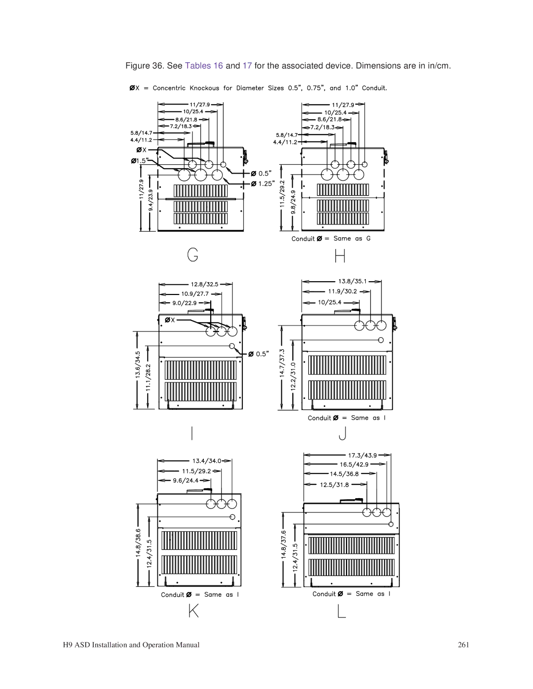
Figure 36. See
Tables 16
and
17
for the associated device. Dimensions are in in/cm.
H9 ASD Installation and Operation Manual
261
Page 268
Page 270
Page 269
Image 269
Page 268
Page 270
Contents
Installation and Operation Manual
Page
H9 Adjustable Speed Drive
Important Notice
Introduction
Manual’s Purpose and Scope
About This Manual
Toshiba International Corporation
Contacting Toshiba’s Customer Support Center
Table of Contents
256
246
263
265
Signal Words
General Safety Information
Safety Alert Symbol
Qualified Personnel
Special Symbols
Equipment Warning Labels
Disposal
Equipment Inspection
Handling and Storage
Mounting Requirements
Installation Precautions
Location and Ambient Requirements
Conductor Routing and Grounding
Grounding Capacitor Switch
Protection
Power Connections
Personnel Protection
System Integration Precautions
System Setup Requirements
Operational and Maintenance Precautions
Motor Characteristics
Motor/Load Combinations
Power Factor Correction
Light Load Conditions
Motor Braking
Load-produced Negative Torque
Using Vector Control
H9 ASD Characteristics
Over-current Protection
ASD Capacity
Installation Notes
Installation and Connections
Mounting the H9 ASD
Typical circuit breaker configuration
Power Connections
Connecting the H9 ASD
Power Connection Requirements
Grounding Capacitor
System Grounding
Page
Model
Lead Length Specifications
Nema MG-1-1998 Section IV Part
Frequency Compliant Motors
Control
Circuit Config
Term. Name Input/Output
O1A/B OUT1
Terminal Descriptions
Page
TB1 TB2 TB3
Discrete Input
Circuit Configurations
H9 ASD typical connection diagram
Typical Connection Diagram
Startup and Test
EOI Remote Mounting
EOI Operation
H9 ASD Electronic Operator Interface features
EOI Features
LED/LCD Display Information
LED Display
Active Frequency
LCD Display
LED/LCD Display Installation Note
Remote Keypad Required Hardware
Keypad Installation Precautions
Keypad Remote Mounting
Keypad Remote Mounting w/o the ASD-MTG-KIT
Keypad Mounting Dimensions
Keypad Bezel Plate Mounting Dimensions
Keypad Remote Mounting using the ASD-MTG-KIT
Command Control F003
Command Mode and Frequency Mode Control
Frequency Control F004
Command and Frequency Control Selections
Override Operation
Frequency Control Selections
Command Control Selections
Binary/BCD Input Option
Root Menus
System Configuration and Menu Options
Frequency Command Mode
EOI Command Mode
Frequency
Monitor Mode
Page
Main Monitor Selections
Frequency Settings
Settings
Standard Mode
Accel/Decel #1
Analog Output
Input Terminal Delays
Terminals
Input Special
Input Terminals
Line Power Switching
Output Terminals
Reach Settings
Display Parameters
Prohibition
Type Reset
Alarm Prohibition
Real-time Clock Setup
Trip History read-only
Contrast
Changed From Default
Trip History
Main Monitor
Low Current Settings
Selections
View Trace Data
Trip Settings
Phase Loss
Overtorque
Parameters
Jog Settings
Disable
Preset Speeds
Analog Filter
Setpoints
Speed Reference
Acc/Dec #1 #4
Crane/Hoist Settings
Acc/Dec Special
Carrier Frequency
Frequency Control
Five Point Setting
Special Parameters
Jump Frequencies
Traverse
Operation Panel
Motor Set #2
Motor Set #3
Torque Control
Vector Motor Model
Manual Torque Limit
Feedback Settings
Torque Limit Settings
Torque Speed
Limiting
Override Control
PG Settings
My Function Selection
My Function Unit
F906
My Function Monitor
My Function Data
My Function Analog
Communication
Adjustments
Preset Speed
Ethernet Settings
Operation Mode
Group
F571
Pattern Run
Operation Time
Change Password
Enter Password
Speeds
Lockouts
Run Next Time? ⇒ Go to Program Mode
Initial Setup
System Operation
Startup Wizard Parameters
Startup Wizard Parameter Requirements
Manually Configure the ASD
Motor RPM
Display Unit
Operation Local
Changed From Default screen
Default Setting Changes
Save User Settings
F000 F001
Direct Access Parameters/Numbers
Automatic Acceleration/Deceleration
Automatic Torque Boost
F004
Command Mode
FM Terminal Setup Parameters
FM Output Terminal Adjustment
F005 F006
FM Output Terminal Function
Direct Access Number F008
Direct Access Number F007
F007 F008
Forward/Reverse Run Selection
Acceleration Time
F009
Acceleration
Deceleration Time
Upper Limit Frequency
F012 F015
Lower Limit Frequency
Pattern
Direct Access Number F016
Motor Overload Protection Configuration
F016 F017
Manual Torque Boost
Preset Speed Truth Table
Preset Speed
Preset Output
F018 F019
F020 F024
F040
Direct Access Number F040
Automatic Function Selection
Program ⇒ Utilities ⇒ Display Parameters
F100 F105
Low-Speed Signal Output Frequency
Speed Reach Frequency
Speed Reach Detection Band
Direct Access Number F107
Direct Access Number F106
F106 F107
Input Terminal Priority
F109
F114
Direct Access Number F120
Direct Access Number F119
F119 F121
Input Terminal 9 LI1 Function
Input Terminal 12 LI4 Function
F122 F124
Input Terminal 13 LI5 Function
Input Terminal 14 LI6 Function
Input Terminal 15 LI7 Function
F125 F131
Input Terminal 16 LI8 Function
Output Terminal 1 OUT1 Function
Output Terminal 3 FL Function
F132 F134
Output Terminal 4 OUT3 Function
Output Terminal 5 OUT4 Function
Output Terminal 6 R1 Function
Direct Access Number F135
F135 F137
Output Terminal 9 R2 Function
F138 F142
Input Terminal 1 F Response Time
Input Terminal 2 R Response Time
F143 F165
Input Terminal 19 B14 Function
F166 F169
Input Terminal 20 B15 Function
Output Terminal 10 R3 Function
Motor Overload Protection Level
F170 F173
Base Frequency Voltage
Direct Access Number F175
Direct Access Number F174
Direct Access Number F176
F174 F177
Direct Access Number F179
Direct Access Number F178
Direct Access Number F180
F178 F181
Program ⇒ Special ⇒ V/f Five-Point Setting
Five-Point Setting Frequency
Direct Access Number F190
F190
Direct Access Number F191
Five-Point Setting Voltage
Direct Access Number F192
F191 F192
F193 F197
Direct Access Number F199
Direct Access Number F198
Direct Access Number F200
F198 F200
Input Speed Control Setup
Input Point 1 Setting
F201
Speed Control
F202 F204
Input Point 2 Setting
Input Point 1 Frequency
Input Point 2 Frequency
F205
Input Torque Control Setup
Input Point 1 Rate
Torque Control
Input Point 2 Rate
Frequency Mode Priority Switching Frequency
F206 F208
F209
Direct Access Number F209
Analog Input Filter
Program ⇒ Frequency ⇒ Analog Filter
RR Input Speed Control Setup
RR Input Point 1 Setting
F210
RR Input Point 1 Frequency
Direct Access Number F212
RR Input Point 2 Setting
Direct Access Number F213
F212 F213
F214 F215
RR Input Torque Control Setup
RR Input Point 1 Rate
RR Input Point 2 Rate
RX Input Speed Control Setup
RX Input Point 1 Setting
F216 F217
RX Input Point 1 Frequency
Direct Access Number F218
RX Input Point 2 Setting
Direct Access Number F219
F218 F219
F220 F221
RX Input Torque Control Setup
RX Input Point 1 Rate
RX Input Point 2 Rate
F222
RX2 AI1 Input Point 1 Setting
RX2 AI1 Input Speed Control Setup
F223 F225
RX2 AI1 Input Point 2 Setting
RX2 AI1 Input Point 1 Frequency
RX2 AI1 Input Point 2 Frequency
RX2 AI1 Input Point 1 Rate
RX2 AI1 Input Torque Control Setup
F226
RX2 AI1 Input Point 2 Rate
Direct Access Number F227
F227
F228
BIN Input Point 1 Setting
BIN Input Speed Control Setup
F229 F231
BIN Input Point 2 Setting
BIN Input Point 1 Frequency
BIN Input Point 2 Frequency
PG Input Speed Control Setup
PG Input Point 1 Setting
F234 F235
PG Input Point 1 Frequency
F236 F241
PG Input Point 2 Setting
PG Input Point 2 Frequency
Start Frequency
F242 F251
F252 F256
Set the Command Mode Selection F003 to EOI Keypad
Jog Setup and Execution
Direct Access Number F260
F260
Direct Access Number F261
Panel Operation Jog Mode
Direct Access Number F262
F261 F262
Direct Access Number F264
Setup Requirements
Up/Down Frequency up Mode Up/Down Frequency down Mode
F264
F265 F269
Program ⇒ Special ⇒ Jump Frequencies
Direct Access Number F270
F270
Jump Frequency 1 Bandwidth
F271 F287
Jump Frequency 2 Bandwidth
Jump Frequency 3 Bandwidth
F288 F293
Auto Restart Selection
F294
PWM Carrier Frequency
Ridethrough Setup Requirements
Regenerative Power Ridethrough Mode
F302
Program ⇒ Protection ⇒ Undervoltage/Ridethrough
Retry Selection
Direct Access Number F303
F303
Overvoltage Limit Operation
F304 F305
Supply Voltage Correction
F307 F310
Dynamic Braking Resistance
Continuous Dynamic Braking Capacity
Random Mode
Forward Run/Reverse Run Disable
Carrier Frequency Control Mode
F311 F317
F318 F322
Drooping Insensitive Torque
F323 F329
Drooping Output Filter
Light-Load High-Speed Operation
F330 F334
F335 F341
F342 F346
Creeping Time
F347 F349
Braking Time Learning Function
Accel/Decel Suspend
Acceleration Suspend Frequency
F350 F353
Acceleration Suspend Time
Deceleration Suspend Frequency
Program ⇒ Terminal ⇒ Line Power Switching
Commercial Power/ASD Output Switching
Switching Setup Requirements
F354
F355 F359
F360 F364
F365 F370
F371 F376
F377 F401
Autotuning
PG Disconnection Detection
Simple Positioning Completion Range
Motor Rated Capacity
F402 F409
Motor Rated Current
Motor Rated RPM
F410 F415
F416 F423
Torque Command Selection
Stall Prevention Factor
Tension Torque Bias Input
Load Sharing Gain Input
F424 F426
Forward Speed Limit Input
Forward Speed Limit Level
Reverse Speed Limit Input
F427 F431
Reverse Speed Limit Input Level
Speed Limit torque=0 Center Value Reference
Power Running Torque Limit 1 Level
Power Running Torque Limit
F432 F441
Speed Limit torque=0 Band
F442 F446
F447 F452
F453 F463
F464 F471
Speed PID Switching Frequency
Second Speed Loop Stabilization Coefficient
Input Bias
RR Input Bias
F472 F475
RR Input Gain
RX Input Bias
RX2 AI1 Input Bias
F476 F479
RX2 AI1 Input Gain
AI2 Option V/I Input Bias
Direct Access Number F501
Direct Access Number F500
F498 F501
Permanent Magnet PM Motor Constant
Direct Access Number F502
Program ⇒ Special ⇒ Accel/Decel #1 #4 Settings
F502
Acc/Dec Pattern
F503
Direct Access Number F503
Acc/Dec Pattern 1
Accel/Decel Switching Frequency
F504 F505
Pattern Acceleration Upper Limit Adjustment
Pattern Acceleration Lower Limit Adjustment
Pattern Deceleration Lower Limit Adjustment
Pattern Deceleration Upper Limit Adjustment
Acceleration/Deceleration Pattern
Acceleration/Deceleration Switching Frequency
F511 F514
Pattern Operation Selection
Pattern Operation Mode
F515 F521
Pattern 1 Repeat
Direct Access Number F522
F522
Program ⇒ Pattern Run ⇒ Speeds
F523
Pattern Group 1 Selection
Direct Access Number F525
Direct Access Number F524
Direct Access Number F526
Direct Access Number F527
Pattern 2 Repeat
F528 F531
Pattern Group 2 Selection
F532 F535
Direct Access Number F537
Direct Access Number F536
Direct Access Number F538
Direct Access Number F539
F540 F545
F546 F551
F552 F560
Preset Speed Operation Mode
Speed 13 Operation Time
Speed 14 Operation Time
Preset Speed 2 Operation Mode
Preset Speed 1 Operation Mode
Preset Speed 3 Operation Mode
F561 F563
F564 F573
Preset Speed 15 Operation Mode
Preset Speed 14 Operation Mode
Retain Trip Record at Power Down
F574 F602
ASD Output Phase Failure Detection
Emergency Off Mode Settings
F603 F605
Emergency Off DC Injection Application Time
F606 F610
Low Current Detection Threshold
F611 F615
Low Current Trip Threshold Time
Short Circuit Detection At Start
F616 F621
F622 F627
F628 F630
Regenerative Power Ridethrough Control Level
Undervoltage Trip Detection Time
Brake Answer Wait Time
Factory Default Thermal Detection + Overload
Direct Access Number F631
F631
ASD Overload
460-Volt Carrier Frequency/Thermal Derating Specifications
Annual Average Ambient Temperature
Analog Input Broken Wire Detection Level
F633 F637
Rush Relay Current Activation Time
PTC2 Thermal Selection
F638 F641
Braking Resistance Overload Time 10x rated torque
Step-Out Current Detection Level
Direct Access Number F661
Direct Access Number F660
F660 F661
Adding Input Selection
AM Terminal Setup Parameters
AM Output Terminal Adjustment
F669 F671
Selection of OUT Terminal
F672 F674
MON1 Terminal Adjustment
MON1 Terminal Meter Selection
MON2 Terminal Meter Selection
F675 F682
F683 F689
F690 F700
F701 F705
Display Gradient Characteristic
Display Units for Voltage and Current
Display Unit Multiplication Factor
F706
Operation Command Clear Selection When ST Off
Display Bias
Change Step Selection
F721 F729
F730 F737
Trace Selection
F740 F742
Trace Cycle
Trace Data
F743 F801
Baud Rate RS485 2-wire
Parity RS485 2- and 4-wire
Communications Time-Out Action RS485 2- and 4-wire
Communications Time Out Time RS485 2- and 4-wire
F802 F804
ASD Number
ASD-to-ASD Communications RS485 2-wire
Send Wait Time RS485 2-wire
RS485 2-Wire Protocol Selection
F805 F807
Gain and Bias Settings
Point 1 Setting
F810 F812
Frequency Point Selection
Baud Rate RS485 4-wire
Point 2 Setting
RS485 Send Wait Time RS485 4-wire
F813 F825
RS485 4-Wire Protocol Selection TSB/ModBus
ASD-to-ASD Communications RS485 4-wire
Communications Option DeviceNet/Profibus Setting
F826 F830
F831 F836
F841 F844
F845 F853
Preset Speed Operation Selection
Disconnection Detection Extended Time
ASD Operation at Disconnect
F854 F871
Communications Option Speed Switch Monitor DeviceNet
CC-Link
Block Write Data
Direct Access Number F876
Direct Access Number F875
Direct Access Number F877
F875 F877
Input Function Command
Network Option Reset Settings
F878 F901
Free Notes
Output Function Assigned
F902 F905
F906 F910
F911 F915
My Function Percent Data
F916 F919
My Function Frequency Data
F920 F925
My Function Time Data
F926 F930
My Function Count Data
F931 F935
F936 F940
F941 F945
F946 F950
Direct Access Number F952
Direct Access Number F951
Direct Access Number F953
Direct Access Number F954
Direct Access Number F956
Direct Access Number F955
Direct Access Number F957
Direct Access Number F958
Analog Function Assigned Object
F959 F962
Analog Input Function Target
Monitor Output Function
Monitor Output Function Command
F964 F966
Direct Access Number F968
Direct Access Number F967
Direct Access Number F969
F967 F969
Direct Access Number F971
Direct Access Number F970
Direct Access Number F972
F970 F971
Virtual Input Terminal 1 Selection
F973 F976
Virtual Input Terminal 2 Selection
Virtual Input Terminal 3 Selection
F977
Setup example
My Function
Combined Terminal Function
234
F980 F984
Sel. No
Terminal Selection Descriptions
PID Differentiation/Integration Clear Clears the PID value
External Over-heat Causes an Over-Heat Trip OH
No NC
Selections
Selection Communications Terminal Assignment Number
My Function Input Target selections
Input Param Function
Setting
Trace Back Data Selections
Number
Comm Monitor
Input Setting/Communication Number Function Resolution
F928 F932 for My Function Data
My Function Operator selections
Alarms and Trips
Alarms, Trips, and Troubleshooting
User Notification Codes
Alarms
Atn
DbOn
Dynamic Braking Resistor
Type Reset required select Clear run timer
With the Low-current Trip
PtSt
LED Display LCD Display Possible Causes
Trips/Faults
EF1/EF2
50/E-51
None
ETN
OCA3 or OCL
OCA1 or OCL
OCA2 or OCL
OP1
Clearing a Trip
Viewing Trip Information
Enclosure Dimensions
Enclosure Dimensions and Conduit Plate Information
412K 415K
410K
420K
425K
See Tables 16 and 17 for actual dimensions
259
260
261
See for the associated device. Dimensions are in in/cm
Ph Variable
Current/Voltage Specifications
Motor HP
VT130H9U Continuous Seconds ± 2 Hz Frequency
4160
4055 4080
4220
4270
Wire/Cable Size Lug Size Range Terminal Board Torque
Cable/Terminal/Torque Specifications
MCP Rating AWG or kcmil Number Amps VT130H9U
Model
4270 4330 4400
In-Lbs./Nm
4055
Short Circuit Protection Recommendations
Dynamic Braking Resistor Wire/Cable Specifications
269
Part Identifier Device Name Device Function
H9 ASD Optional Devices
Index
272
273
274
275
276
277
278
279
280
Toshiba
Top
Page
Image
Contents