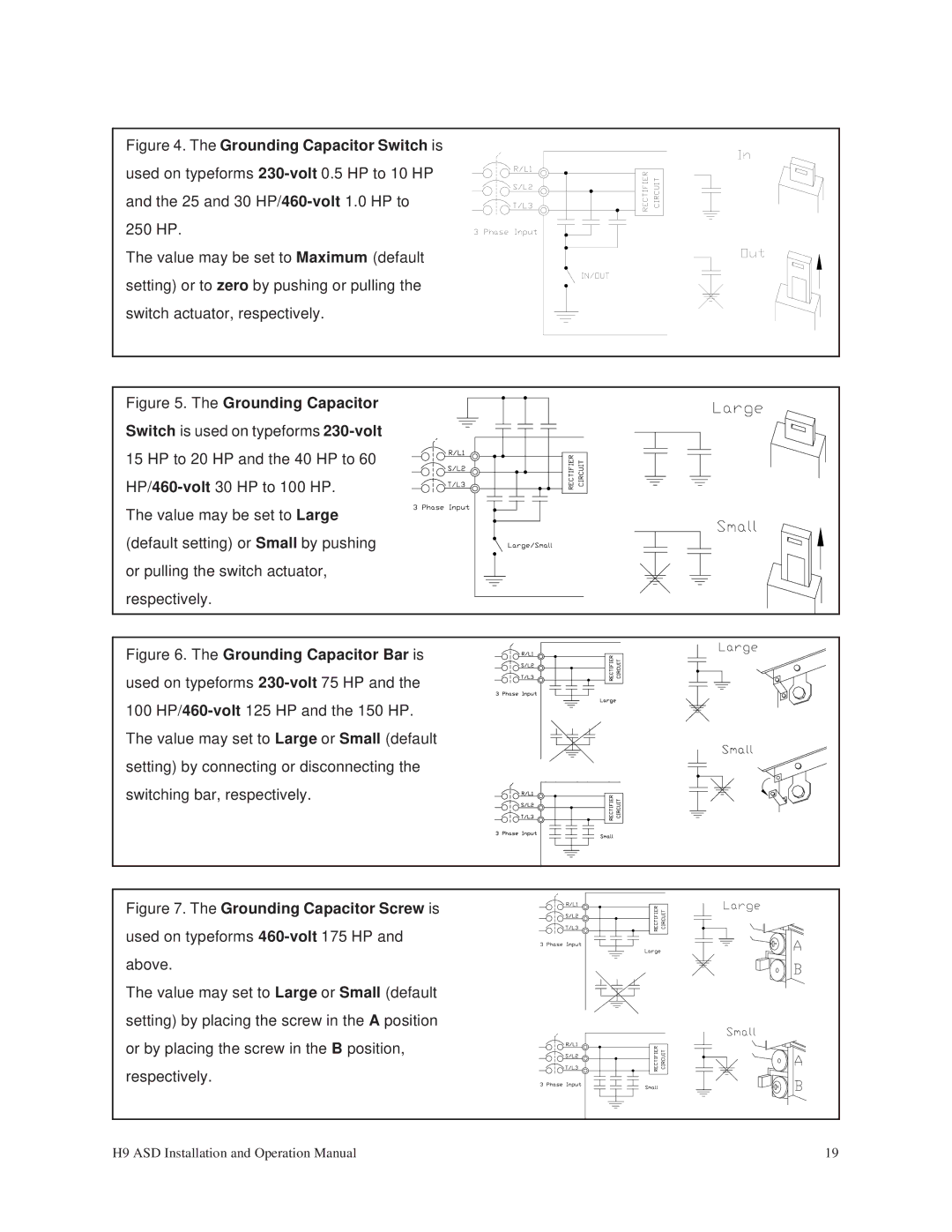
Figure 4. The Grounding Capacitor Switch is used on typeforms 230-volt 0.5 HP to 10 HP and the 25 and 30 HP/460-volt 1.0 HP to 250 HP.
The value may be set to Maximum (default setting) or to zero by pushing or pulling the switch actuator, respectively.
Figure 5. The Grounding Capacitor Switch is used on typeforms 230-volt 15 HP to 20 HP and the 40 HP to 60 HP/460-volt 30 HP to 100 HP.
The value may be set to Large (default setting) or Small by pushing or pulling the switch actuator, respectively.
Figure 6. The Grounding Capacitor Bar is used on typeforms 230-volt 75 HP and the 100 HP/460-volt 125 HP and the 150 HP.
The value may set to Large or Small (default setting) by connecting or disconnecting the switching bar, respectively.
Figure 7. The Grounding Capacitor Screw is used on typeforms 460-volt 175 HP and above.
The value may set to Large or Small (default setting) by placing the screw in the A position or by placing the screw in the B position, respectively.
H9 ASD Installation and Operation Manual | 19 |
