Network Interface Connections
Topology Issues For each segment of the network, you need to decide what type of cable and fiber to use. Table
Table | Fiber Type and Distance Restrictions |
|
|
| |
|
|
|
|
|
|
| Fiber | Wavelength | Physical Rate | Data Rate | Maximum Cable |
| Type | (nm) | (GHz) | (MBps) | Length |
| (microns) |
|
|
| (meters) |
|
|
|
|
|
|
| 50/125 | 850 | 1.0625 | 106.25 | 450 |
| (Short Wave) | 850 | 2.1250 | 212.50 | 260 |
|
| ||||
| 62.5/125 | 850 | 1.0625 | 106.25 | 250 |
| (Short Wave) | 850 | 2.1250 | 212.50 | 120 |
|
| ||||
| 9/125 | 1300 | 1.0625 | 106.25 | 10000 |
| (Long Wave) | 1300 | 2.1250 | 212.50 | 10000 |
|
| ||||
|
|
|
|
|
|
Connecting Fibre Channel Cabling
NOTE: The installer must ensure the correct optical transceiver is used on the UltraNet Edge equipment.
Use this section to connect the cabling for the UltraNet Edge 3000 Fibre Channel interface.
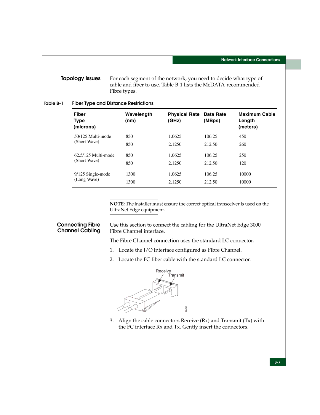
The Fibre Channel connection uses the standard LC connector.
1.Locate the I/O interface configured as Fibre Channel.
2.Locate the FC fiber cable with the standard LC connector.
Receive
Transmit
Sb040
3.Align the cable connectors Receive (Rx) and Transmit (Tx) with the FC interface Rx and Tx. Gently insert the connectors.