User Guide
Copyright 2005-2006 McDATA Corporation. All rights reserved
Record of Revisions and Updates
Contents
Chapter Building a Custom Edge 3000 Chassis
Chapter Configuring an EPort Extension over an Ethernet WAN
Chapter Configuring an FPort Extension over an Ethernet WAN
Chapter Configuring Ficon Extension
Chapter Configuring an EPort Extension over an ATM WAN
FC/SCSI Tape Pipelining
Chapter Configuring Tape Device Extension
Hardware Maintenance
Product Support and Software Maintenance
13-3
Troubleshooting and Diagnostics
13-8
13-10
Appendix a Site Preparation
Appendix B Installation and Cabling
Appendix D Advanced UCM Configurations
Appendix C Cables, Connectors, and Adapters
Appendix F Configure Snmp
Appendix G Resetting the System to Factory Defaults
Issuing the Spantree Portfast Command
Appendix H Manual Configuration of the Initial IP Settings
Appendix J Configuration Worksheets
Contents Xii
Figures
Figures Xiv
Tables
Tables
Organization
Preface
UltraNet Edge Storage Router 3000 User Guide
Xix
Related Documentation
Conventions This guide uses the following conventions
UltraNet Edge Storage Router Command Reference
Fax 720
Forwarding Publication Comments
Laser Compliance Statement
Regulatory and Safety Statements
United States and Canada UL Certification
European Union EMC and Safety Declaration N-Mark
Argentina UL Certification
German GS Mark
Russian Gost Certification
Xxix
Xxx
General Precautions
ESD Precautions
Introducing the UltraNet Edge
Introduction
McDATA UltraNet Edge 3000 User Guide
UltraNet Edge 3000 Benefits
Fibre Channel
UltraNet Edge 3000 Features
ATM Forum UNI ATM Forum AAL-5
Ethernet 10/100
Gigabit Ethernet
OC-3
Configuration
OC-3/STM-1
Management
UltraNet Edge 3000 Security
McDATA UltraNet Edge 3000 User Guide
UltraNet Edge 3000 Featurization
Hardware Configurations
Configuration requirements
Component/Feature Description
4WAN Connectivity Card Option Features
Short wave SFP for OC-3 ATM
Or OC-3 ATM/POS
Typical Configuration of the UltraNet Edge
Pipelining
Configurations
FC/SCSI Tape
Mixed Application Configurations
Valid Hardware Interface Configurations
Configuration Featurized Configurations
Reconfigure UCM and reboot the unit
Fibre Channel port type can be configured in UltraNet
UltraNet Edge Supported Series FC Card Configurations
Fibre Channel Card Dependencies
FC/SCSI Nport Configurations
FC/SCSI Fport Configurations
FC/SCSI EPort to EPort
FC/SCSI FPort to FPort
Ficon Port Configurations
Hardware Components
Internal Fibre Channel Switch Fcsw
2Front View of the UltraNet Edge
Normal
Indicators, Switches, and Interfaces
Index
Function
Network Design
Network Design Criteria
Ethernet Network
Criteria
1Example Ethernet WAN with two UltraNet Edge 3000s
IP Router
Required Network Design Information for an Ethernet Network
UltraNet Edge
Gigabit Ethernet Switches & Routers
10/100 Ethernet Switches & Routers
Fibre Channel Switches
Ethernet Hubs
ATM Network
Required Network Design Information for an ATM Network
Fibre Channel Switches
Dedicated
UltraNet ConfigManager
Network Routing Options
Fail Over
Load Balancing Path for 2x2 Configurations
Load Balancing
Configurations
Switch WWN Proxy
EPort Disk Streaming Network Recommendations
Fail Over Paths for
Supported Storage Device Applications/Protocols
Required Minimum Hardware for EPort Disk Streaming
EPort Disk Streaming Compatibility Matrix
Non-Supported Storage Device Applications/Protocols
Fibre Channel Frame Level CRC
Fibre Channel End to End CRC
Fibre Channel MTU Batching
Minimum Requirements for CRC
Building the Custom Chassis
Building a Custom Edge Chassis
Select the Edge3000 Custom Chassis
Select Build Chassis and click Next
Custom Chassis Wizard Introduction screen appears
Click Next
McDATA UltraNet Edge 3000 User Guide
Select the Fibre Channel interface type
McDATA UltraNet Edge 3000 User Guide
Building a Custom Edge 3000 Chassis
McDATA UltraNet Edge 3000 User Guide
Configuring a 1x1 Ethernet Wide Area Network
Configuring an EPort Extension over an Ethernet WAN
Gathering the IP
Use the following procedures to create a network map for a
Configuration
Adding Nodes for
An Ethernet WAN
McDATA UltraNet Edge 3000 User Guide
Channel Interface
Network Map, the Default Fibre Channel Interface Type
Adding a Fibre
Network Map Area
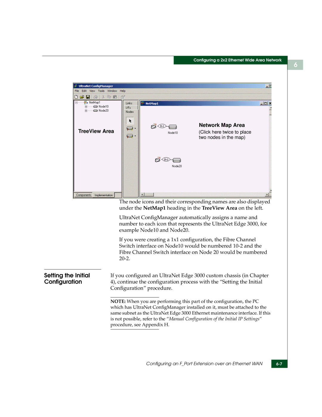
Setting the Initial
Broadcast Data
IP Address of PC running UCM
License Wizard Introduction dialog box appears
Setting the License
Information
McDATA UltraNet Edge 3000 User Guide
Click the IP icon on the center toolbar
License Wizard Finish dialog box appears
Links tab IP icon globe
IP Circuit Wizard Node10 Choose Interface dialog box appears
IP Circuit Wizard Introduction dialog box appears
Drop-down arrow
Click Next
Drop-down arrow
Click Next
Click Next
McDATA UltraNet Edge 3000 User Guide
Configuring an EPort Extension over an Ethernet WAN
Creating a Data
Will complete the configuration process
Path
Following example
Create Data Path Wizard Introduction dialog box appears
McDATA UltraNet Edge 3000 User Guide
Create Data Path Wizard Finish dialog box appears
Delivering the Configured Network
Node10 Properties UltraNet Edge 3000 screen appears
Setting the Delivery
Properties
Delivery Wizard Select Nodes screen appears
Delivery Wizard
Delivery Wizard Introduction screen appears
Delivery Wizard Deliver screen appears
Delivery Wizard Select Operations screen appears
Deliver Network option
Deliver Network
Viewing Logs
Configuring an EPort Extension over an Ethernet WAN
McDATA UltraNet Edge 3000 User Guide
Configuring a 2x2 Ethernet Wide Area Network
Configuring an FPort Extension over an Ethernet WAN
1Sample Fport Ethernet WAN with two UltraNet Edge 3000s
On your desktop or the Start menu
Open the UltraNet ConfigManager software. You can use either
TreeView Area and the Network Map Area
Edge 3000 2x2 1 Gbps Ethernet node type
McDATA UltraNet Edge 3000 User Guide
Switch interface on Node10 would be numbered 10-2
If you were creating a 1x1 configuration, the Fibre Channel
Fibre Channel Switch interface on Node 20 would be numbered
Node icons and their corresponding names are also displayed
Broadcast Data
IP Address of PC running UCM
Repeat through for the second node Node
License Wizard Finish dialog box appears
McDATA UltraNet Edge 3000 User Guide
IP Circuit Wizard Introduction dialog box appears
IP Circuit Wizard Node10 Choose Interface dialog box appears
Click Next
Click Next
Drop-down arrow
Click Next
Click Next
McDATA UltraNet Edge 3000 User Guide
Creating Data Paths for Fibre Channel Switch Interfaces
FC Switch DataPath Wizard Introduction dialog is displayed
Configuring an FPort Extension over an Ethernet WAN
FC Switch DataPath Wizard Finish dialog appears
Configuring an FPort Extension over an Ethernet WAN
Delivering the Configured Network
Delivery Interface defines the IP address by which
Configurations to the nodes
Network map will be delivered
Select the desired option to deliver the network map
Delivery Wizard Introduction screen appears
Configuring an FPort Extension over an Ethernet WAN
Following
Configuring an FPort Extension over an Ethernet WAN
McDATA UltraNet Edge 3000 User Guide
Configuring a 1x1 ATM Wide Area Network
Configuring an EPort Extension over an ATM
Configuration Worksheet from Appendix J will be used
An ATM WAN
Starting UltraNet ConfigManager
McDATA UltraNet Edge 3000 User Guide
Configuring an EPort Extension over an ATM WAN
Received UltraNet Configuration Requests
Broadcast Data
IP Address of PC running UCM
Setting the License
License Wizard Finish dialog box appears
Links tab ATM icon cloud
Adding an ATM
Circuit
ATM Circuit Wizard Introduction dialog box appears
ATM Circuit Wizard Node10 Configure PVC dialog box appears
Active VCI Bits Value Valid Enabled VPI Values
Active VCI Bits Value Valid Enabled VCI Values
Enter the Maximum Burst Size cells/sec in this field
Configuring an EPort Extension over an ATM WAN
ATM Circuit Wizard Node20 Configure PVC dialog box appears
Active VCI Bits Value Valid Enabled VPI Values
McDATA UltraNet Edge 3000 User Guide
Enter the Maximum Burst Size cells/sec in this field
ATM Circuit Wizard Configure Circuit dialog box appears
ATM Circuit Wizard Finish dialog box appears
This procedure will complete the configuration process
After configuring the ATM circuit, you need to establish a
Data Path section in this chapter
Like the following example
Create Data Path Wizard Introduction dialog box appears
McDATA UltraNet Edge 3000 User Guide
Configuring an EPort Extension over an ATM WAN
Create Data Path Wizard Finish dialog box appears
Configuring an EPort Extension over an ATM WAN
Delivering the Configured Network
Delivery Wizard
McDATA UltraNet Edge 3000 User Guide
Deliver Network
Viewing Logs
Configuring Ficon Extension
Configuration IP Address Worksheet will be used as examples
Interface Configurations section in Chapter
Area and the Network Map Area
Drop-down list will appear. Select the type of Fibre Channel
To the Network Map, the Default Fibre Channel Interface Type
Network Map Area
UltraNet Configuration Requests
Process with the Setting the Initial Configuration procedure
Broadcast Data
IP Address of PC running UCM
Setting the License
License Wizard Finish dialog box appears
IP Circuit Wizard Introduction dialog box appears
IP Circuit Wizard Node10 Choose Interface dialog box appears
Click Next
Click Next
Drop-down arrow
Click Next
Click Next
Configuring Ficon Extension
Data Path
After configuring the IP circuit, you need to establish a
Creating a Ficon
Right-click on the icon Double click on the icon
Click Next
Configuring Ficon Extension
Wizard
Using the Ficon
Global Settings
Configuring Ficon Extension
McDATA UltraNet Edge 3000 User Guide
Select Ficon Tape Read Pipelining I/Fs
Configure Ficon Tape Read Pipelining Parameters
Configuring Ficon Extension
McDATA UltraNet Edge 3000 User Guide
Delivering the Configured Network
Delivery Wizard
Configuring Ficon Extension
Deliver Network
Viewing Logs
McDATA UltraNet Edge 3000 User Guide
Setup Prior to Edge Configuration
Configuring Tape Device Extension
Configuration No
Network Configuration Examples
Example
Uni-directional
Using FC/SCSI Tape Pipelining. -1 defines the Fibre Channel
Configuration with
Fibre Channel Switch Zone Device
Bi-directional
Its zone
Channel Switch
Required Fibre
Required Static
Fibre Channel Switch Zone Device FC Switch
Edge LUN Mapping
Automatic DataPath Mapping function of the Edge will
Server a
Rules for Static LUN Mapping World Wide Name Table
Server B
Server C
WWN Filtering
Required Source
Examples of Static Edge LUN Mapping
Channel extended
Device WWN Device Type Lun Source WWN
Configuring Tape Device Extension
Addresses
Configuration process. The worksheet is referred to as
Gathering the IP
Ethernet Maintenance Interface
Default Gateway IP host address for the UltraNet Edge
UltraNet ConfigManager UCM application is used to configure
Icon on your desktop or the Start/Programs menu
Type
Menu and select the Edge3000 1x1 10/100 Mbps Ethernet node
McDATA UltraNet Edge 3000 User Guide
Setting the Initial Configuration
Broadcast Data
IP Address of PC running UCM
Repeat step a through step a for the second node Node
License Wizard Finish dialog box appears
IP Circuit Wizard Introduction dialog box appears
IP Circuit Wizard Node10 Choose Interface dialog box appears
For Node10, enter the IP address labeled
For Node10, enter the gateway address labeled
Drop-down arrow
For Node20, enter the IP address labeled
For Node20, enter the gateway address labeled
Configuring Tape Device Extension
Channel Device
Path for Fibre
Extension Interfaces
On Node10 and the Fibre Channel Device Extension interface
Right-click on the FC interface Double-click
Click Next
Configuring Tape Device Extension
Click Next
Configuring Tape Device Extension
Source WWN
Static Mapping
LUNs and Filtering
Configuring Tape Device Extension
McDATA UltraNet Edge 3000 User Guide
Default is
McDATA UltraNet Edge 3000 User Guide
Mapping Node 20 to WWNs Accessed by Node
McDATA UltraNet Edge 3000 User Guide
Configuring Tape Device Extension
Filtering
Configuring Tape Device Extension
Delivering the Configured Network
Setting the Delivery
Delivery Wizard Select Nodes screen appears
Delivery Wizard Deliver screen appears
Deliver Network
Configuring Tape Device Extension
McDATA UltraNet Edge 3000 User Guide
Buffering, Emulation, and Data Protection
FC/SCSI Tape Pipelining
Buffering
Emulation
How does Buffering Work?
Device Error Recovery UltraNet Edge 3000 Emulation
Fibre Channel Tape Only LUN Mapping
UltraNet Edge 3000 Specific
Target Discovery
Dynamic Target LUN Discovery and LUN Mapping
Overview
10-5
10-6
Upgrading the UltraNet Edge 3000 Software
Product Support Software Maintenance
Snmp Support
Software Version
Verify your Current
Upgrading
UltraNet Edge
Product Support and Software Maintenance
FTP the New UltraNet Edge 3000 Software
Install the New UltraNet Edge Software
Deliver
Remote Dial-up
Mode
11-7
11-8
11-9
Or Higher
Upgrading Edge
Software from
UltraNet WebView Monitoring Application
11-12
Example tm.0x10 upgrade -w wv32.rpm
Displayed in the About UltraNet ConfigManager screen
UltraNet ConfigManager Upgrade
Verify the Current
Version of UltraNet
Upgrading UltraNet ConfigManager Software
UltraNet ConfigManager Upgrade 11-16
Hardware Maintenance
Replacing the UltraNet Edge 3000 Chassis
Front and Rear View of UltraNet Edge 3000 Chassis
Remove the unit from the equipment rack if necessary
Fan Assembly Removal Procedure
Fan Assembly Installation Procedure
Power Supply Removal Procedure
12-6
Top Cover Removal Procedure
Power Supply Installation Procedure
Top Cover Installation Procedure
Fibre Channel Interface Card Removal Procedure
Fibre Channel Interface Card Installation Procedure
10/100 Ethernet Interface Card Removal Procedure
10/100 Ethernet Interface Card Installation Procedure
Gigabit Ethernet Interface Card Removal Procedure
Gigabit Ethernet Interface Card Installation Procedure
OC-3 ATM Interface Card Removal Procedure
OC-3 ATM Interface Card Installation Procedure
Replacing the Gigabit Ethernet Short Wave Transceiver
Removing the Plain Metal Clasp Transceiver
Removing the Gig-E Short Wave SFP Transceiver
Removing the Black Metal Clasp Transceiver
Plastic Tab Transceiver
Installing the Gig-E
Installing the Red
Installing the Plain Metal Clasp Transceiver
Installing the Black Metal Clasp Transceiver
Removing the Blue Metal Clasp Transceiver
Replacing the Gigabit Ethernet Long Wave Transceiver
Removing the Gig-E Long Wave SFP Transceiver
Transceiver into the interface card
Installing the Blue
Replacing the Gigabit Ethernet Copper Transceiver
12-24
Removing the OC-3 ATM Short Wave SFP Transceiver
Replacing the OC-3 ATM Short Wave Transceiver
Installing the Plain
Installing the OC-3
Carefully pull the transceiver out of the interface card
Right port is functional
Removing the OC-3 ATM Long Wave SFP Transceiver
Replacing the OC-3 ATM Long Wave Transceiver
Plain metal clasp. Use the following procedure to install
Replacing the Fibre Channel Short Wave Transceiver
Removing the Black
Installing the Fibre Channel Short Wave SFP Transceiver
Installing the Black Metal Clasp
Removing the Fibre
Replacing the Fibre Channel Long Wave Transceiver
Channel Long Wave
Removing the Blue
Installing the Blue Plastic Tab Transceiver
Installing the Fibre Channel Long Wave SFP Transceiver
Replacing the Fibre Channel Long Wave Transceiver 12-34
User Interface Commands for the UltraNet Edge
Troubleshooting Diagnostics
Basic Troubleshooting for the UltraNet Edge
Ip show Ip fwdtbl
Display the User Interface Commands
Example of the arp tbl command screen display
Sections highlight the commands useful for troubleshooting
Tankio stats
Arp tbl
Amdenet 10/100
Maintenance
WAN or
Amdenet stats
13-5
Gnic3 stats
GNIC3 Gigabit
Ethernet WAN
Troubleshooting and Diagnostics
Fccnt batchstat
Gnic3 auto
Fccnt clear backbone
Clear batchstats
Dump proxy instance
Fccnt proxy
Fcsw switch
Fccnt stats backbone
Fcsw cache
Tm.0x10 fcxl2 fcxl21.0x10 dump backbone
Codes
LED Diagnostic
Vxok
Troubleshooting FC/SCSI Tape Pipelining Device Extension
Basic Troubleshooting Steps for FC/SCSI Tape Pipelining
13-15
Diagnostics
Serial Interface Connection Ethernet Maintenance
Loading Starting Diagnostic Program Exit and Reboot
UltraNet Edge 3000 Diagnostic Programs
Stop
Enadmaint
Fibre Channel
UltraNet Edge 3000’s flash drive as the file fcbb.dll. Using
13-23
Interface Connection in this chapter
Enapoll Nouflo Memcont
Gigabit Ethernet
Ifcs Enapoll PAD SBP RPS Flagerr Rtrip Memcont
Enaint Ownbitena Enapoll
13-28
Flash Drive
UltraNet Edge 3000 Flash Drive diagnostic program resides on
Graceful Shutdown
Site Requirements
Dimensions
Site Preparation
Chassis Clearance
Clearance Requirements
Table A-2 lists the clearance requirements in Figure A-1
Specifications listed in Table A-3
Specifications
Environmental Specification Parameter
Environmental
Type Requirement
Overview
Installation and Cabling
Unpacking and Inspecting the Hardware
UltraNet Edge 3000 Placement
Table-Top
Rack Mount
Flathead Undercut Screws Bracket Ear
Figure B-1Connecting the CAT5 Cable to the UltraNet Edge
Connecting the UltraNet Edge
Sb033
Network Interface Connections
Issues
Cabling
Interface cabling
Connecting Fibre Channel Cabling
Removing Fibre Channel Cabling Fibre Channel Transceivers
Ethernet 10/100
Connecting Gig-E
Interface configuration, cabling and optional transceivers
Cabling
Removing Gig-E
Transceivers
Initial Power-On Procedure
OC-3 ATM Cabling
Figure B-4Power Supply Switch
Serial Interface Cabling Instructions
Maintenance and Diagnostics Connections
Figure B-6PC Connection to Serial Interface
Pin Signal
Type Description
Cables and Equipment
Equipment
Customer-Supplied
Preventing Damage from Electrostatic Discharge ESD
Cables
Specific host and network cables for the external cable
UltraNet Edge Storage Router 3000 User Guide
RS-232 Cables with RJ-45 Connector
Cables, Connectors, Adapters
DB Adapters
Cable Length
RJ-45 Pin Out DB25 Pin Out AA Adapter
DB Adapters Description
Initials Full Name
Table C-5 provides the full names of the pinout initials
RJ-45 Pin Out DB9 Pin Out EE Adapter
Cable Type Specification
Fibre Channel Specifications
Cable Type Specification
Gigabit Ethernet Specifications
Ethernet 10/100 Specifications
Gigabit Ethernet Specifications
OC-3 SONET/SDH STM-1
OC-3 ATM Specifications
Cable Type Specification
UltraNet Edge Storage Router 3000 User Guide
Advanced UCM Configurations
Only
Fcsw Tab 2 port
FC Switch Tab
Domain ID
Switch Priority
Destination Node
Ratov in mS
Edtov in mS
Enable Disk Streaming
Ar Number
BBCredits
Time Synchronization Protocol
Configure the Time
Synchronization
Protocol
Time Synchronization Protocol screen appears
UltraNet Edge Expanded View screen appears
From the Time Synchronization Protocol screen, select None
Transport CRC Checking
Enable/Disable EPort Disk Streaming
EPort Disk Streaming Settings
Enable/Disable FPort Disk Streaming
FPort Disk Streaming Settings
Fibre Channel Switch Interface dialog appears
Fibre Channel Interface screen appears
FPort Disk Streaming Settings
UltraNet Edge Storage Router 3000 User Guide
Display Static Routes
Modifying Static Routes
Verify Static Routes
Click the Static Routes tab
Delete Static Routes
Modify Static Routes
Add Static Routes
Configure Snmp
Configure Snmp on the UltraNet Edge
UltraNet Edge Storage Router 3000 User Guide
Page
UltraNet Edge Storage Router 3000 User Guide
Field Description
Authentication Traps
Destination field
Snmp Software Packages
UltraNet Edge Storage Router 3000 User Guide
Using the Sysclean Command
Resetting the System to Factory Defaults
Overview of the Sysclean Command
Bits per sec
At the prom level, type sysclean
UltraNet Edge Storage Router 3000 User Guide
Manual Configuration Initial IP Settings
Prom setNetCfg 192.168.10.1, 192.168.10.3
Update UltraNet ConfigManager with the Manual Configurations
Change the Precedence field from Preferred to Default
UltraNet ConfigManager with the Manual Configurations
UltraNet Edge Storage Router 3000 User Guide
Issuing the Spantree Portfast Command
Using the Spantree Portfast Command for Cisco Routers
Where
Modnum Number of the module
Console enable set spantree portfast 1/2 enable
Configuration Worksheets
Configuration Worksheets
Hardware configuration
IP Configuration
Worksheet
See Figure for an example, along with the relationship to
Configuration Worksheets
Worrksheet
Configuration Worksheets
UltraNet Edge Storage Router 3000 User Guide
Glossary
Eport
Fault tolerant
Electrostatic discharge
Ethernet
Gateway
FLport
Gigabit Ethernet
Hub
ISCSI
Message Authentication
Isochronous
Local Area Network
Nport
Mirroring
NLport
Node number
RS-232
Router
Simple Network
Management Protocol
Striping
Storage Area Networking
Subnet
Synchronous
Zoning
AA B-14,C-2 DB C-2 EE B-14,C-3
Index
ATM/POS
OC-3 ATM/POS
OC-3 ATM
Index
UltraNet Edge Storage Router 3000 User Guide