Sysmac CQM1H Series
Serial Communications Board
Omron
Omron Product References
About this Manual
Name Cat. No Contents
Table of Contents
Communications for 11 Data Links 107
Precautions
General Precautions
Safety Precautions
Intended Audience
Application Precautions
Operating Environment Precautions
Xiv
Applicable Directives
Conformance to EC Directives
Concepts
Conformance to EC Directives
Recommended Mounting Method
Recommended Ferrite Cores
Section
Overview
Features
Model Number
Serial Communications Boards
System Configuration
Mounting Location
Protocol Overview
Sending C-mode Host Link Commands
Host Link Mode
Protocol Macros
Slave-initiated Communications
4 PC 11 Data Links
No-protocol Communications
NT Links -- 11 Mode
NT Links -- 1N Mode
Basic Operating Procedure
Specifications
General Specifications
Serial Communications Board
Board Components and Installation
Board Indicators
Indicators
Indicator Color Status Meaning
Component Names and Functions
CPU Unit Indicators
Connector Pin Layout
2 RS-232C Port
Tions method Wire Wire, 1N Synchroniza
Applicable Connectors
3 RS-422A/485 Port
Recommended Cables
Switches
Terminating Resistance Switch Wire or 4-Wire Switch
Label Name Settings Factory setting
Mounting the Board
Installation
Mounting Height and Connector Cover Dimensions
External Dimensions
Precautions in Handling the Board
Connectors
Wiring
Standard Connectors For Both RS-232C RS-422A/485
Recommended Cables RS-232C Cables
Wiring Precautions
Reducing Electrical Noise for External Wiring
RS-422A/485 Cable
WiringSection
Pin Function Factory Setting
Recommended RS-232C Wiring Examples
Wire Connections
Recommended RS-422A/485 Wiring Examples
Recommended RS-422A/485 Cable
Model Manufacturer CO-HC-ESV-3Px7/0.2 Hirakawa Hewtech Corp
Using a 3G2A9-AL001 Link Adapter
Using an NT-AL001-E RS-232C/RS-422 Link Adapter
Length Model
Wiring Connectors
Cable Preparation
Shield Connected to Hood FG
Shield Not Connected to Hood FG
Soldering
Assembling Connector Hood
Connecting to the Board
Default Settings and Related Bits/Flags
Contents Addresses
PC Setup Settings
Words Bits Function Applicable Mode
Word Bits Function Communications Modes
Control Bits, Flags, and Status Information
00 to Port
Slot 1 Inner Board Error Code Hex
Word Bits Function Inner Board Error Flag
Host Link Communications
TXD-- Instruction
Host Link Communications
Serial communications Features Mode
Host Link Communications
Simultaneous Usage of Both Ports
Host Link Specifications
Application Procedure
Port Bits Default Function Setting
PC-initiated Communications TXD-- Instruction
Host-initiated Communications Host Link Commands
Connections
Port Configura Schematic diagram Tion RS-232C
Types of Connection
Connection Examples
RTS RS-232C
Using NT-AL001-E Converting Link Adapters
1N Connections Using RS-232C Ports
Connections Using RS-422A/485 Ports
1N Connections Using RS-422A/485 Ports
Standard Cables from Board to Personal Computer
Preparing an RS-232C Cable for the Computer
Board port Computer Network type Model Length Remarks Port
Protocol
Normal Response Frame
Format
FCS Frame Check Sequence
Error Response Frame Format
Computer
Communications Sequence
Using the TXD-- Instruction
Example Programs
Example Program for
TXD-- Application Example
Communications Control Signals Communications Timing
Setting a Transmission Delay
Header code PC mode Name
Host Link Commands
End Codes
End Contents Probable cause Corrective measures Code
RS-232C Ports
Changes from Previous Products
Full-duplex transmissions that do not use
Half-duplex transmissions that use CD
2 RS-422A/485 Ports
Protocol Macros
Overview of the Protocol Macro Functions
Protocol Macro Function Specifications
Step common Per sequence Parameters Transmission
Sequence contents Number of steps
Control
Parameters Response
Error processing
Step contents Commands
Repeat counter
Retry count
Tents Header Stant Terminator Data attrib Utes Con
Description Message con Con
Data attrib Stant
Utes of ad Vari
Using the Protocol Macro Function
Using the Standard System Protocols
Be traced
SEND&RECEIVE
Modifying Standard System Protocols
Restrictions in Using the CX-Protocol
Restriction Procedure
Storage Memory
Select Transfer to PLC via Online or
Port Bits Setting Function
Using Standard System Protocols
Using User-created Protocols
Send Data
Receive Data
Transferring the created project to the Board
Port Configuration Schematic diagram
Connecting RS-232C Ports Connections to E5CK Controller
Connections to a Modem
DIP SW
485 RS-422A Terface Hood
3G2A9-AL001
Receive
Protocol Structure
Parameter Meaning
Sequence Parameters
Step Parameters
Level Setting
Level Possible changes in settings
Protocol Data Error Flag
Board Identification Error Flag hardware error
Port 2 Protocol Macro Execution Error Flag
Port 1 Protocol Macro Execution Error Flag
Port 1 Communications Error Flag
Word Bits Name and Function Classifi Set Reset Cation
Port 2 Communications Error Flag
Port 1 Sequence Abort Completion Flag
Port 2 Protocol Macro Error Code
Port 1 Protocol Macro Error Code
Port 2 Tracing Flag
Port 1 Executed Reception Case No. code
Port 1 Continuous Trace Start/Stop Bit
Port 2 Restart Bit
Port 2 Continuous Trace Start/Stop Bit
Port 1 Shot Trace Start/Stop Bit
Port 2 Transfer Step Error Processing Flag
Port 1 Transfer Step Error Processing Flag
Port 1 Sequence END Completion Flag
Port 1 Forced Abort Bit
PMCR-- Instruction Specifications
Using Protocol Macros
Error Codes
Executing Communications Sequences
First Receive Data
Flags
Storage Word D
PMCR-- Operation
Ladder Program Structure
Operand Areas and Address Ranges
Programming Example
Connections
Ladder Program Example
Send Word Allocation for Sequence No Present Value Read
Receive Word Allocation for Sequence No Present Value Read
Operand Settings for the PMCR-- Instruction
Ladder Programming Example
Precaution on Reception Failures for Pmcr
Transmission Methods
Error Flags for Overrun, Framing, and Parity Errors
Time Lag t1
Baud rate b/s Lag time ms
Processing When a Sequence Ends Abnormally
Example
Precautions on Using the Force Abort Bit
No-protocol Communications
Specification
No-protocol Specifications
Start code End code Yes
Send/Receive Message Frames
100
Connecting to a Bar Code Reader via RS-232C
Transmit TXD-- in No-protocol Mode
Using No-protocol Communications
Transmit TXD-- and Receive RXD
Control Word C
Receive RXD-- in No-protocol Mode
RXD-- Communications Procedure
TXD-- Communications Procedure
Computer Settings
PC Settings
Application Example
Conditions
Communications for 11 Data Links
Port Bits Function Setting
PC Setup Setting
Starting Data Links
OverviewSection
Specifications
Overview
Master PC Settings
Using 11 Data Links
Slave PC Settings
Conditions
NT Link Communications
NT Links 11 Mode
NT Links 1N Mode
Precautions
Overview of NT Links
115
NT Link Settings for 11 Mode
NT Link Settings for 1N Mode
117
118
Troubleshooting and Maintenance
Indicators Possible cause Remedy Board CPU Unit
Front-panel Indicator Error Displays
Troubleshooting
Board Error Information
Serial Communications
122
123
124
Board ReplacementSection
126
Not perform
Error Indicator Error details Cause Remedy Code
128
3 1N NT Link Mode
Cleaning
Cleaning and Inspection
Materials Required Daily
Inspection
Materials Required Occasionally
Inspection Items
Board Replacement
Settings after Replacing the Board
Replacement Procedure
Protocol Macros Designed with CX-Protocol
Procedure
Using Standard System Protocols
Introduction
Example
Standard System Protocols
Receive Data Word Allocation 4th Operand
Protocol name Function
System Configuration for Standard System Protocol
CompoWay/F Master Protocol
CompoWay/F
Transmission Procedure
Communications Specifications
Command and Response Formats
Command Format
Command Frame Contents
Response Frame Contents
Appendix B
Command Data contents Code
Command Frame
Example
End code Name Meaning
Variable type Contents
Command and Text
Example Variable Area Read
Response Text
Structure of the Protocol
CompoWay/F Master Protocol Sequences
CompoWay/F Message Frames and PMCR260 Operands
Send with Ascii Conversion, with Response Sequence No
Response Frame
Receive Data Word Allocation 3rd Operand of PMCR260
Send Data Word Allocation 2nd Operand of PMCR260
145
Broadcast with Ascii Conversion, No Response Sequence No
Send with No Conversion and with Response Sequence No
Broadcast with No Conversion and No Response Sequence No
149
150
RS-232C
Connections
RS-485 2-wire Connections
RS-422 4-wire Connections
E5jK Digital Controller Read Protocol
Appendix C
Connection Configuration
RS-232C Connection
RS-485 Connection
Read Set Point during SP Ramp Sequence No
Read Process Value Sequence No
Appendix C
Send Data Word Allocation 2nd Operand of Pmcr
Read Alarm Value Sequence No
Read MV Sequence No
Read Set Point Sequence No
Read Cooling Coefficient Sequence No
Read Dead Band Sequence No
Read Manual Reset Value Sequence No
Read Hysteresis Sequence No
Read Control Period Sequence No
Read SP Ramp Time Unit and Set Value Sequence No
Read LBA Detection Time Sequence No
Read MV Limits Sequence No
Read MV at Stop Time and at PV Error Sequence No.013
Read Alarm Hysteresis Sequence No
Read Input Digital Filter Sequence No
Read Input Shift Limits Sequence No
Read Level 0 Parameters Sequence No
Read Level 1 Parameters 1 Sequence No
Read Level 1 Parameters 2 Sequence No
166
Read Level 2 Parameters 1 Sequence No
Read Level 2 Parameters 2 Sequence No
169
General-purpose Read Sequence No
E5jK Digital Controller Write Protocol
Appendix D
Write Set Point Sequence No
Write Alarm Value Sequence No
Write Cooling Coefficient Sequence No
Write Manual Reset Value Sequence No
Write Dead Band Sequence No
Write Hysteresis Sequence No
Write Control Period Sequence No
Write SP Ramp Time Unit and Set Value Sequence No
Appendix D
Write MV at Stop Time and at PV Error Sequence No
Write LBA Detection Time Sequence No
Write MV Limits Sequence No
Write Alarm Hysteresis Sequence No
Write Input Digital Filter Sequence No
Write Input Shift Value Sequence No
Write Level 0 Parameters Sequence No
Write Level 1 Parameters 1 Sequence No
Write Level 1 Parameter 2 Sequence No
Write Level 2 Parameters 1 Sequence No
Write Level 2 Parameters 2 Sequence No
General-purpose Write Sequence No
Switch to Level 0 Software Reset Sequence No
Remote/Local Sequence No
Run/Stop Sequence No
Execute/Cancel AT Sequence No
Software Reset Sequence No
Switch to Level 1 Sequence No
Appendix E
E5ZE Temperature Controller Read Protocol
RS-232C Connections
Signal name Signal direction Pin No Brevi Ation
RS422/485 Connections RS-485
Pin No Signal name Abbreviation Signal direction
RS-422A
Appendix E
Communications Parameter DIP Switch
Switch Settings
Unit Number Switch
Baud Rate DIP Switch
192
Read Output Values Sequence No
Read Set Point, Process Value, and Output Value Sequence No
195
196
Read Alarm Mode Sequence No
Read Output Mode Sequence No
Read Alarm Temperatures Sequence No
Read Operation Status Sequence No
Read Setting Unit Sequence No
Read Error Status Sequence No
Read Input Shift Value Sequence No
Read Ramp Value Sequence No
Read Output Value Limit Sequence No
Read Present Set Point Sequence No
Read Output Value Change Rate Limit Sequence No
Read HB Alarm and HS Alarm Valid Channels Sequence No
Read Heater Current and SSR Leakage Current Sequence No.121
Read Dead Band/Overlap Band Sequence No
208
Appendix F
E5ZE Temperature Controller Write Protocol
Write Set Point Setting Unit 1 Sequence No
Write Set Point Setting Unit 0.1 Sequence No
212
213
Write Alarm Mode Sequence No
Write Output Mode Sequence No
Write Alarm Temperature Setting Unit 1 Sequence No
Write Alarm Temperature Setting Unit 0.1 Sequence No
Start Autotuning Sequence No
Write Setting Unit Sequence No
Cancel Autotuning Sequence No
Appendix F
Write Manual Output Value Sequence No
Write Ramp Value Sequence No
Write Output Value Limit Sequence No
Write Output Value Change Rate Limit Sequence No
Initialize Settings Sequence No
Save Settings Sequence No
Write HB and HS Alarm Valid Channels Sequence No
Write Dead Band/Overlap Band Sequence No
Stop Operation or Control Sequence No
Start Control Sequence No
Start Manual Operation Sequence No
Appendix G
E5jJ Temperature Controller Protocol
RS422A/485 Connections
Signal name Abbreviation Signal direction Pin No
Appendix G
Input Signal ground
Select Local Mode Sequence No
Select Remote Mode Sequence No
Select Backup Mode Sequence No
Select RAM Write Mode Sequence No
Write Parameters 1 Sequence No
Save Set Point Sequence No
Write Parameters 2 Sequence No
235
Read Parameters 1 Sequence No
Read Parameters 2 Sequence No
238
Read Set Point Limit Sequence No
Read Output Value Sequence No
Read Initial Status Sequence No
Read Heater Current Sequence No
241
242
ES100j Digital Controller Protocol
Appendix H
Appendix H
RS-422A/485 Connections
Appendix H
Read Event Data Sequence No
Read Time Signal Sequence No
Read Error Detection Data Sequence No
249
Read Heater Burnout Data Sequence No
Read PV Data Sequence No
Read SP Data Sequence No
Read MV Data Sequence No
Read Control Monitor Data Sequence No
255
Read Adjustment Parameters Sequence No
257
258
Write Adjustment Parameters Sequence No
Read PID Control Parameters 1 Sequence No
261
Read PID Control Parameters 2 Sequence No
263
Write PID Control Parameters 1 Sequence No
265
Write PID Control Parameters 2 Sequence No
Read Local SP Sequence No
268
Write Local SP Sequence No
Read Program Parameters Sequence No
271
Write Program Parameters Sequence No
Remote Setting Mode Sequence No
External Setting Mode Sequence No
Local Setting Mode Sequence No
Run Command Sequence No
Auto Mode Sequence No
Reset Stop Sequence No
Execute A.T. Sequence No
Manual Mode Sequence No
Cancel A.T. Sequence No
Change Bank No. Sequence No
Change Pattern No. Sequence No
Read Controller Status Sequence No
General-purpose Command Sequence No
282
Protocol Configuration
K3Tj Intelligent Signal Processor Protocol
Appendix
Ladder Interface Settings
Sequence Communications Function Ladder interface
Send word Receive word Allocation
Signal name Abbreviation Pin No Direction
K3T j Intelligent Signal Processor Protocol
Inverting output Input or output Non-inverting output
Signal name Abbreviation Signal direction Terminal
Reset Control Continuous Units Sequence No
Reset by Unit Number Sequence No
289
Write Set Value L Continuous Units Sequence No
Write Set Value H Continuous Units Sequence No
Write Set Value LL Continuous Units Sequence No
Write Set Value with Bank by Unit Number Sequence No
Write Set Value HH with Bank Continuous Units Sequence No
Write Set Value L with Bank Continuous Units Sequence No
Write Set Value H with Bank Continuous Units Sequence No
Write Set Value LL with Bank Continuous Units Sequence No
Write Set Value O5 with Bank Continuous Units Sequence No
Write Set Value O2 with Bank Continuous Units Sequence No
Write Set Value O1 with Bank Continuous Units Sequence No
Read Set Value by Unit Number Sequence No
Read Set Value H Continuous Units Sequence No
Read Set Value HH Continuous Units Sequence No
Read Set Value L Continuous Units Sequence No
Read Set Value LL Continuous Units Sequence No
Read Set Value with Bank by Unit Number Sequence No
Read Set Value H with Bank Continuous Units Sequence No
Read Set Value HH with Bank Continuous Units Sequence No
Read Set Value L with Bank Continuous Units Sequence No
Read Set Value LL with Bank Continuous Units Sequence No
Read Set Value O2 with Bank Continuous Units Sequence No
Read Set Value O3 with Bank Continuous Units Sequence No
Read Set Value O1 with Bank Continuous Units Sequence No
Read Holding Data Sequence No
Read Holding Data PH Continuous Units Sequence No
Offset Contents Data
Read Holding Data BH Continuous Units Sequence No
Read Display Value PV by Unit Number Sequence No
300
Model Data Read by Unit Number Sequence No
Read Display Value PV Continuous Units Sequence No
Model Data Read Continuous Units Sequence No
303
V500/V520 Bar Code Reader Protocol
Appendix J
Appendix J
V520 Connections
V500 Connections
V500-C11 BCR Functions
System Setting
Host Interface
V520-R121
BCR Read Stop Sequence No
BCR Read Start Sequence No
Data Read Sequence No
Complete Data Read Sequence No
CODE93
BCR Function Write V500 Sequence No
BCR Function Read V500 Sequence No
Log Data Output Request V500 Sequence No
BCR Connection Confirmation V500 Sequence No
Preset Data Set V500 Sequence No
Data Continuous Read Scan V500 Sequence No
Log Data Clear V500 Sequence No
Data Continuous Read Interrupt V500 Sequence No
BCR Initialize V500 Sequence No
General-purpose Command 1 Sequence No
General-purpose Command 2 Sequence No
Data Continuous Read Interrupt V520 Sequence No
Receive Data Storage Word Allocation 3rd Operand of Pmcr
Appendix J
3Z4L Laser Micrometer Protocol
Appendix K
Appendix K
319
3Z4L-3000 Series DIP Switch
DIP Switch Settings
3Z4L-4000 Series DIP Switch
Setting Status
3Z4L-3000 Series
Delimiter Control Code Setting 3Z4L-4000 Series
322
Offset Contents Data Data format Series
Memory Switch Set Sequence No
3Z4L Clear Sequence No
Mm Unit Set Sequence No
Calibration Release Sequence No
Calibration Set Sequence No
Measurement Condition Set 3000-series Sequence No
Program Number Set 3000-series Sequence No
326
327
Measurement Condition List Request 3000-series Sequence No
Measurement Condition Release 3000-series Sequence No
329
330
Single Run Measurement Start 3000-series Sequence No
Zero Run Measurement Start 3000-series Sequence No
Continuous Measurement Start Scan 3000-series Sequence No
Measurement Termination 3000-series Sequence No
Data Request 3000-series Sequence No
Statistic Processing Execution 3000-series Sequence No
All Statistic Memory Clear 3000-series Sequence No
Statistic Processing Non-execution 3000-series Sequence No
Statistic Processing Memory Clear 3000-series Sequence No
Statistic Result Request 3000-series Sequence No
Appendix K
Offset Contents Data Data format
Memory Switch Set 1 3000-series, High-speed Type Sequence No
Memory Switch Set 2 3000-series, High-speed Type Sequence No
337
338
3Z4L Initialize 3000-series Sequence No
Measurement Condition Set 4000-series Sequence No
341
Measurement Condition List Request 4000-series Sequence No
Measurement Condition Release 4000-series Sequence No
Single Run Measurement Start 4000-series Sequence No
Continuous Measurement Start Scan 4000-series Sequence No
Deflection Measurement Start 4000-series Sequence No
Data Request 4000-series Sequence No
Continuous Measurement Termination 4000-series Sequence No
Forced Positive Zero 4000-series Sequence No
Forced Negative Zero 4000-series Sequence No
General-purpose Command 1 4000-series Sequence No
General-purpose Command 2 4000-series Sequence No
Visual Inspection System Protocol
Appendix L
Appendix L
For RS/CS Flow Control
Pin No Signal name Abbreviation
Offset Content data format Data
Measurement Execution F200 Sequence No
Continuous Measurement Execution Scan F200 Sequence No
Continuous Measurement Execution Interrupt F200 Sequence No
Reference Object Registration Group F200 Sequence No
Reference Object Registration Criterion F200 Sequence No
Evaluation Condition Change F200 Sequence No
Arbitrary Measurement Value Acquisition F200 Sequence No
Measurement Execution F300 Sequence No
Continuous Measurement Execution Scan F300 Sequence No
358
Continuous Measurement Execution Interrupt F300 Sequence No
360
Measurement Execution and Positioning F350 Sequence No
Illumination Fluctuation Follow Execution F300 Sequence No
Camera Designation and Positioning F350 Sequence No
Scene Switching and Positioning F350 Sequence No
Camera Change Decrease by 1 F200/300 Sequence No
Scene Switching Decrease by 1 Sequence No
Reset F200/300 Sequence No
Scene Switching Increase by 1 Sequence No
Camera Change Increase by 1 F200/300 Sequence No
General-purpose Command Send Sequence No
Scene Switching Arbitrary Sequence No
General-purpose Command Send/Receive Sequence No
Measurement, Inspection Termination Sequence No
366
V600/V620 ID Controller Protocol
Appendix M
Appendix M
369
RS-422A Connections
DIP Switch
V600/620-CD1D DIP Switches
372
V600-CAjA DIP Switches
Read ASCII/1 Sequence No
Read ASCII/2 Sequence No
Read ASCII/4 Sequence No
Read ASCII/8 Sequence No
Read Hexadecimal/1 Sequence No
Read Hexadecimal/2 Sequence No
Read Hexadecimal/4 Sequence No
Read Hexadecimal/8 Sequence No
Auto-read ASCII/1 Sequence No
Polling Auto-read Ascii Sequence No
Auto-read Hexadecimal/1 Sequence No
Polling Auto-read Sub-command ASCII/2 Sequence No
Polling Auto-read Sub-command ASCII/4 Sequence No
Polling Auto-read Sub-command ASCII/8 Sequence No
Polling Auto-read Hexadecimal Sequence No
Polling Auto-read Sub-command Hexadecimal/2 Sequence No
Polling Auto-read Sub-command Hexadecimal/4 Sequence No
Polling Auto-read Sub-command Hexadecimal/8 Sequence No.517
Write ASCII/1 Sequence No.518
Write ASCII/2 Sequence No
388
Write ASCII/4 Sequence No
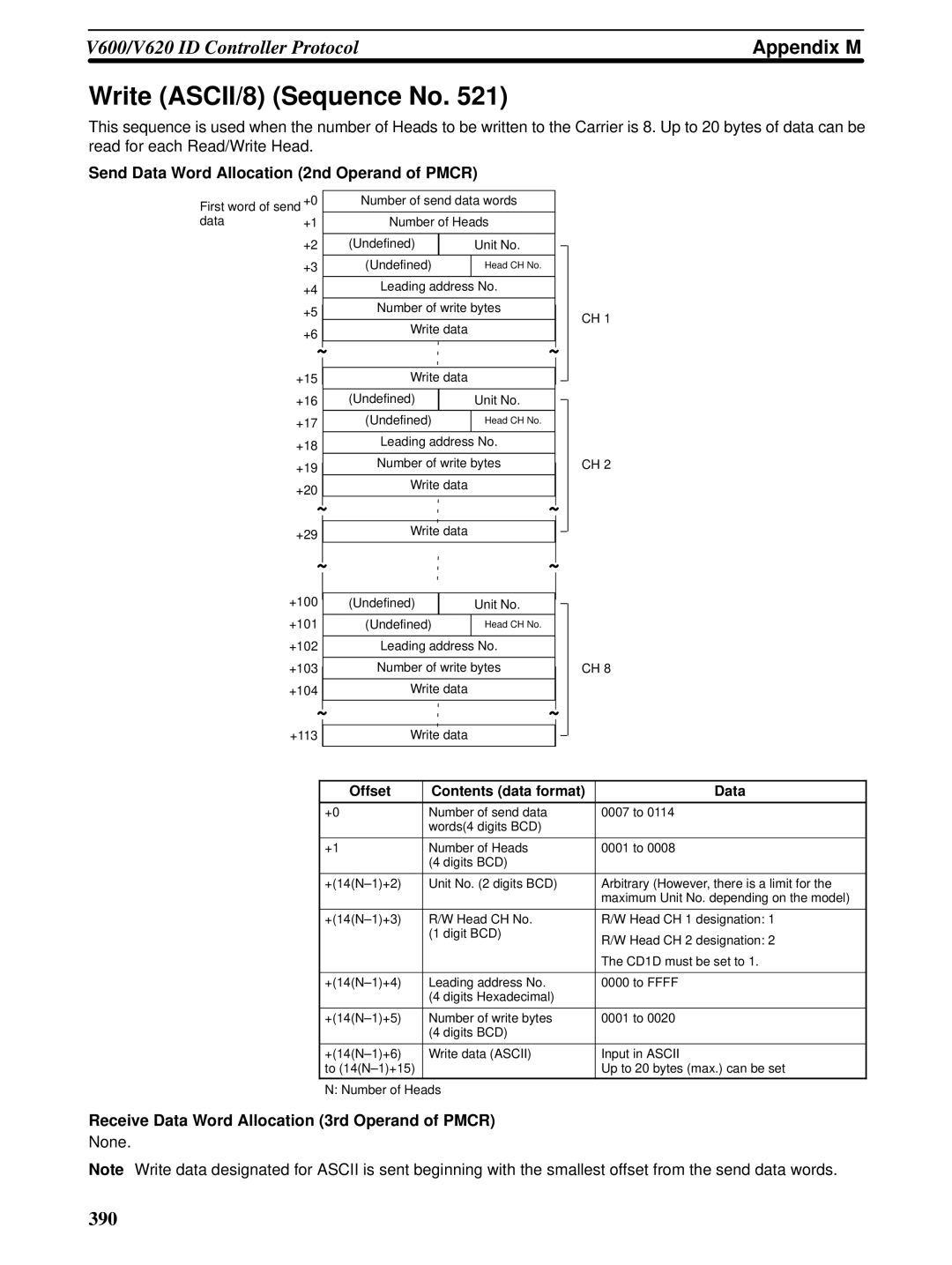
Write ASCII/8 Sequence No
Write Hexadecimal/1 Sequence No
Write Hexadecimal/2 Sequence No
Write Hexadecimal/4 Sequence No
Write Hexadecimal/8 Sequence No
Auto-write ASCII/1 Sequence No
Auto-write Hexadecimal/1 Sequence No
Polling Auto-write ASCII/2 Sequence No
Polling Auto-write Subcommand ASCII/4 Sequence No
Polling Auto-write Subcommand ASCII/2 Sequence No
Polling Auto-write Subcommand ASCII/8 Sequence No
Polling Auto-write ASCII/4 Sequence No
Polling Auto-write Subcommand Hexadecimal/4 Sequence No
Polling Auto-write Subcommand Hexadecimal/2 Sequence No
Polling Auto-write Hexadecimal/2 Sequence No
Polling Auto-write Hexadecimal/4 Sequence No
Polling Auto-write Subcommand Hexadecimal/8 Sequence No
Polling Auto-write Hexadecimal/8 Sequence No
Data Check Sequence No
Control Sequence No
Command Processing Cancel Sequence No
Error Information Read Sequence No
Polling Auto-write Command Processing Cancel Sequence No
Polling Auto-read Command Processing Cancel Sequence No
402
Appendix N
Hayes Modem AT Command Protocol
Compatible Modems
Modem Settings
Dialling
Operand and Word Settings of Pmcr
Setting Example
Password Verification
Password Verification Operation
Data Send/Receive
Operand
Escape Mode
Hang Up Command
Communication Errors
Numbers
Index
413
414
415
416
417
Revision code Date Revised content
Revision History
Original production
Authorized Distributor