Router modules | 1 |
Management module LEDs
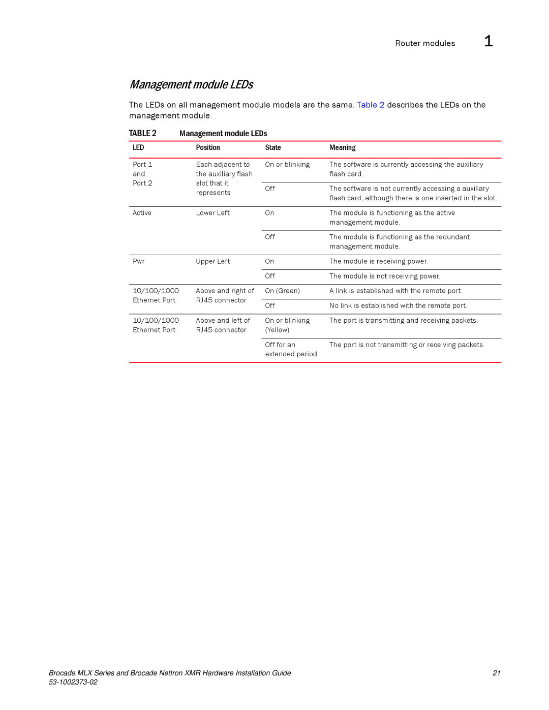
The LEDs on all management module models are the same. Table 2 describes the LEDs on the management module.
TABLE 2 | Management module LEDs |
| ||
|
|
|
| |
LED | Position | State | Meaning | |
|
|
|
| |
Port 1 | Each adjacent to | On or blinking | The software is currently accessing the auxiliary | |
and | the auxiliary flash |
| flash card. | |
Port 2 | slot that it |
|
| |
Off | The software is not currently accessing a auxiliary | |||
| represents | |||
|
| flash card, although there is one inserted in the slot. | ||
|
|
| ||
|
|
|
| |
Active | Lower Left | On | The module is functioning as the active | |
|
|
| management module. | |
|
|
|
| |
|
| Off | The module is functioning as the redundant | |
|
|
| management module. | |
|
|
|
| |
Pwr | Upper Left | On | The module is receiving power. | |
|
|
|
| |
|
| Off | The module is not receiving power. | |
|
|
|
| |
10/100/1000 | Above and right of | On (Green) | A link is established with the remote port. | |
Ethernet Port | RJ45 connector |
|
| |
Off | No link is established with the remote port. | |||
|
| |||
|
|
|
| |
10/100/1000 | Above and left of | On or blinking | The port is transmitting and receiving packets. | |
Ethernet Port | RJ45 connector | (Yellow) |
| |
|
|
|
| |
|
| Off for an | The port is not transmitting or receiving packets. | |
|
| extended period |
| |
|
|
|
| |
Brocade MLX Series and Brocade NetIron XMR Hardware Installation Guide | 21 |
|