The following table describes the system LED indications.
Table
LED | Color | Description |
|
|
|
Power Supply (PWR) | Green Static | The switch is turned on. |
| OFF | The switch is turned off. |
|
|
|
Redundant Power Supply (RPS) | Green Static | The RPS is currently operating. |
(models: 3524 and 3548 ) |
|
|
| Red Static | The RPS failed. |
| OFF | The redundant power supply is not plugged in. |
|
|
|
Redundant Power Supply (RPS) | Green Static | The RPS is currently operating. |
(models: 3524P and 3548P ) |
|
|
| OFF | The redundant power supply has failed or is not |
|
| plugged in. |
|
|
|
Diagnostics (DIAG) | Green Flashing | The system diagnostic test is currently in progress. |
| Green Static | The system diagnostic test passed successfully. |
| Red Static | The system diagnostic test failed. |
| OFF | The system is operating normally. |
|
|
|
Temperature (TEMP) | Red Static | The device has crossed the permitted temperature |
|
| range. |
| OFF | The device is operating within the permitted |
|
| temperature range. |
|
|
|
Fan (FAN) | Green Static | All device fans are operating normally. |
| Red Static | One or more of the device fans is not operating. |
|
|
|
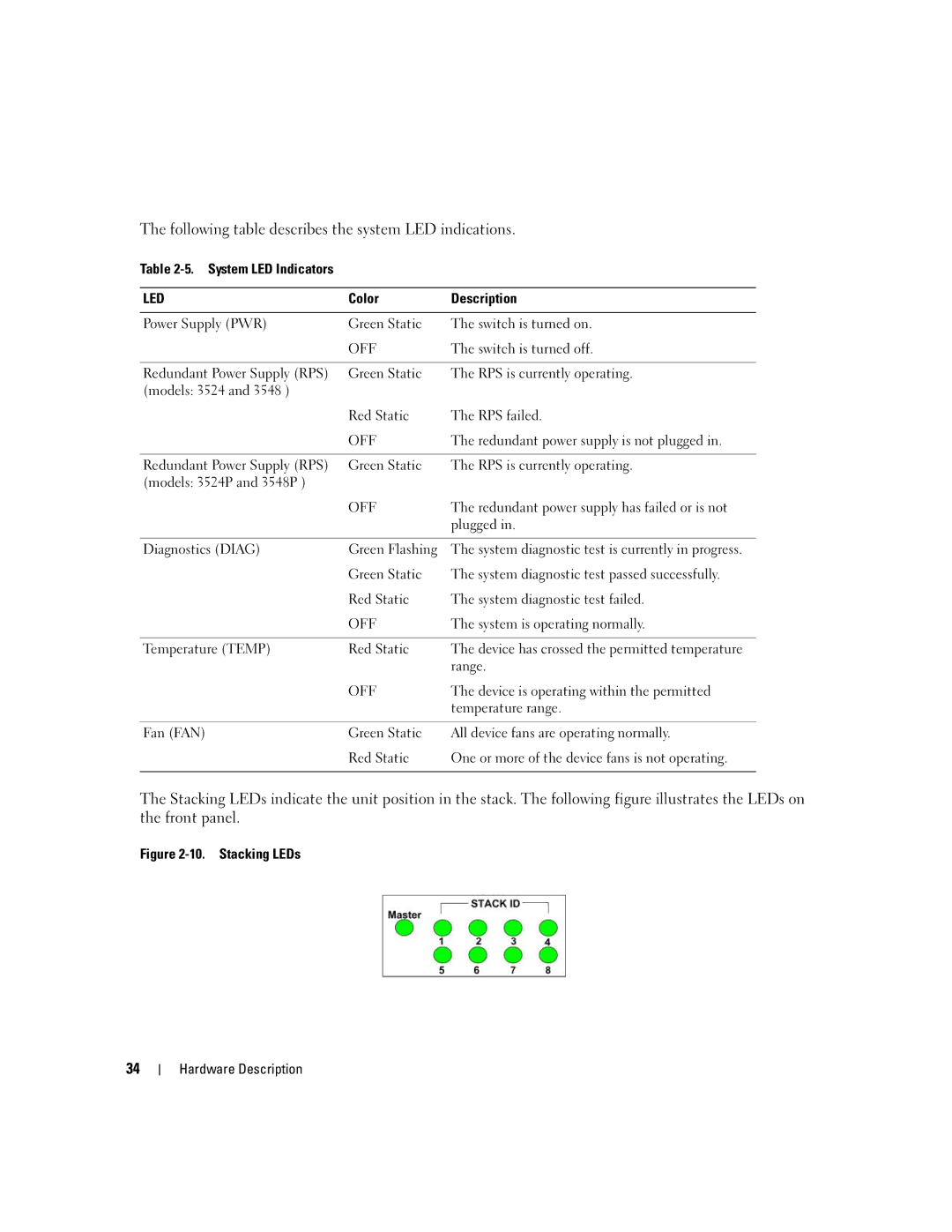
The Stacking LEDs indicate the unit position in the stack. The following figure illustrates the LEDs on the front panel.
Figure 2-10. Stacking LEDs
34
