There are two buttons on the front panel. The Stack ID button is used to select the unit number. The second button is the Reset Button which is used to manually reset the device. The Reset button does not extend beyond the unit’s front panel surface, so reset by pressing it accidentally is prevented. On the front panel are all the device LEDs.
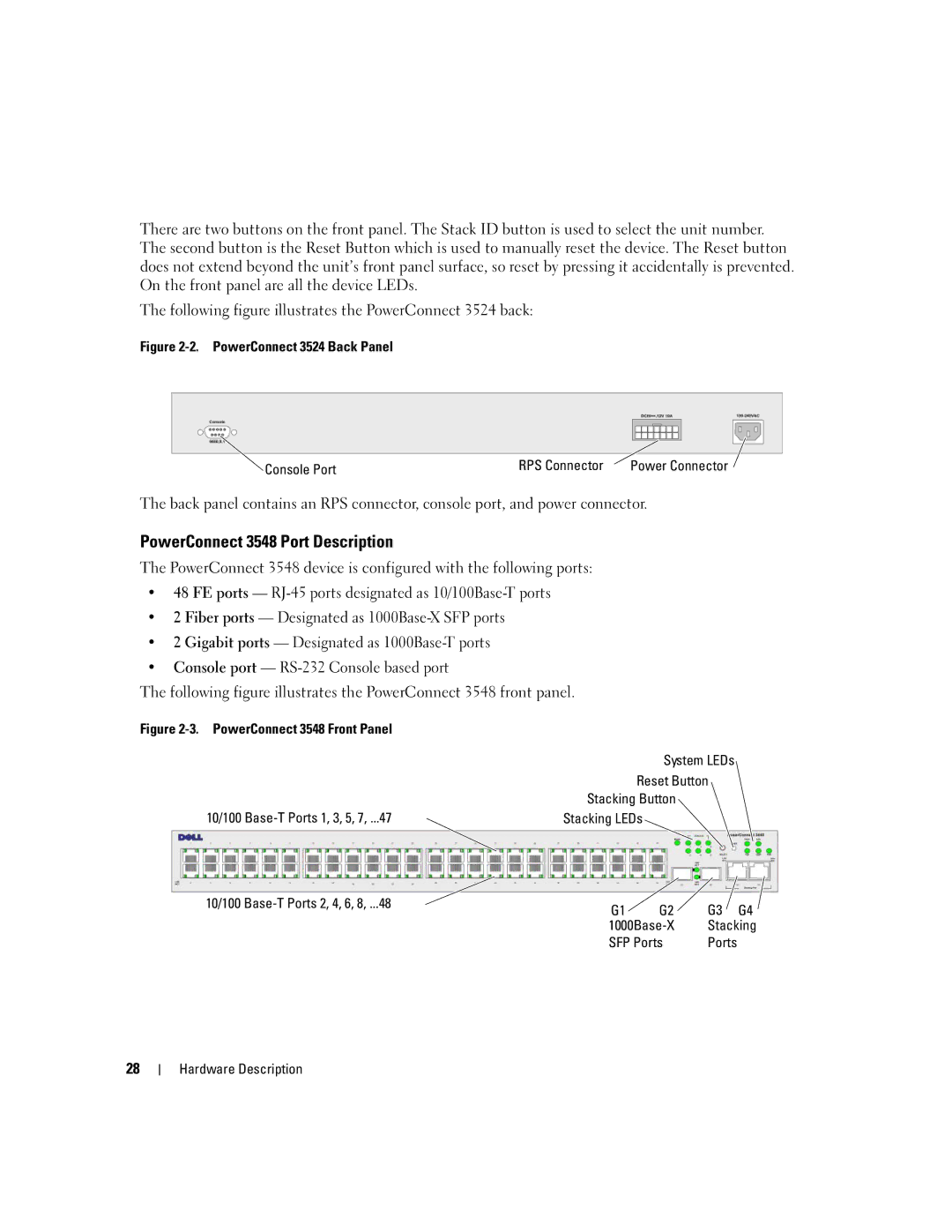
The following figure illustrates the PowerConnect 3524 back:
Figure 2-2. PowerConnect 3524 Back Panel
Console Port | RPS Connector | Power Connector |
|
|
The back panel contains an RPS connector, console port, and power connector.
PowerConnect 3548 Port Description
The PowerConnect 3548 device is configured with the following ports:
•48 FE ports —
•2 Fiber ports — Designated as
•2 Gigabit ports — Designated as
•Console port —
The following figure illustrates the PowerConnect 3548 front panel.
Figure |
|
| System LEDs |
| Reset Button |
| Stacking Button |
10/100 | Stacking LEDs |
10/100 | G1 | G2 | G3 | G4 |
| ||||
| Stacking | |||
| SFP Ports | Ports |
| |
28
Hardware Description