DSP56301 User’s Manual
Revision 3, March
How to reach us
USA/EUROPE
Japan
ASIA/PACIFIC
Page
Page
Contents
Chapter Memory Configuration
Chapter Core Configuration
Chapter Programming the Peripherals
Chapter Host Interface HI32
Chapter Enhanced Synchronous Serial Interface Essi
Chapter Serial Communication Interface SCI
Index
Chapter Triple Timer Module
Chapter a Bootstrap Program Chapter B Programming Reference
Figures
DSP56301 User’s Manual
Xii
Pulse Width Modulation Toggle Mode, TRM =
DSP Control Register Dctr DSP PCI Control Register Dpcr
Tables
Tables
Essi Clock Sources
Manual Organization
Overview
High True/Low True Signal Conventions
Signal/Symbol Logic State Signal State Voltage
Manual Conventions
Ground2
Ground
PIN is a generic term for any pin on the chip
DSP56300 Core Features
Size Cache
Program RAM Instruction Data RAM Switch Size Cache Size
CE = MS =
DSP56300 Core Functional Blocks
Data ALU
Multiplier-Accumulator MAC
Address Generation Unit AGU
Data ALU Registers
Program Control Unit PCU
PLL and Clock Oscillator
Jtag TAP and OnCE Module
On-Chip Memory
DSP56301 Switch Memory Configuration
Internal Buses
Expansion Area
DMA
Memory Expansion Area
General-Purpose Input/Output Gpio signals
Peripherals
Host Interface HI32
Enhance Synchronous Serial Interface Essi
Triple Timer Module
Serial Communications Interface SCI
Related Documents and Web Sites
DSP56301 Documentation
Name Description Order Number
DSP56300FM/AD
DSP56301 Functional Signal Groupings
Timers JTAG/OnCE Port
Enhanced Synchronous Serial Interfaces ESSI0
ESSI1
Port a
See -2for a listing of the Host Interface/Port B Signals
DSP56301
Host Interface/Port B Detail Signal Diagram
Power
Power Inputs
Ground Signals
Ground
Clock Signals
Phase-Lock Loop Signals
Clock
PLL
External Memory Expansion Port Port a
External Address Bus
External Data Bus
External Bus Control
Signals are tri-stated
Arbitration is reset to the bus slave state
Output Tri-stated Is an active-low output that is
Output Tri-stated Is asserted for half a clock
CAS
Bclk
Interrupt and Mode Control
Interrupt and Mode Control
Signal State Type During Signal Description Name
Nonmaskable Interrupt-After
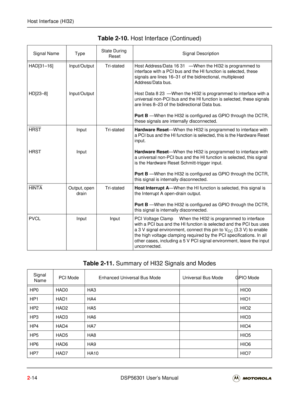
Host Interface HI32
10.Host Interface
Command 0-3/Byte Enable 0-3 -When the HI32 is programmed
HBS
Hpar
Hdak
Hperr
Hserr
Hirq
Hstop
HWR
11.Summary of HI32 Signals and Modes
Signal PCI Mode Enhanced Universal Bus Mode Gpio Mode Name
HP8 HAD8 HD0 HIO8 HP9 HAD9 HD1 HIO9
HAD10 HD2 HIO10
HAD11 HD3 HIO11
HAD12 HD4 HIO12
Gpio
12.Host Port Pins HI32
PCI
Bus Command/Byte Enable Host Address Bus
Host Target Ready Host Data Bus Enable
Reserved
Host Initiator Ready Host Data Bus Direction
Parity Error DMA Request
Bus Grant Host Address Enable
Host Device Select Host Select Acknowledge
Host Lock Bus Strobe
Host System Error Host Interrupt Request
Bus Request Host Transfer Acknowledge
Hreq is deasserted in the same PCI
Hstr
Hstop HWR/HRW
Host Stop Host Write/Read-Write
HRD/HDS
Initialization Device Select Host Read/Data Strobe
Host Bus Clock
Address/Data Multiplexed Bus Data Bus
Hardware Reset
Enhanced Synchronous Serial Interface
Host Interrupt a
Active low, open drain output pin
13.Enhanced Synchronous Serial Interface
PC0
PC1
PC2
SCK0
PC3
SRD0
PC4
14.Enhanced Serial Synchronous Interface
PD0
PD1
PD2
SCK1
PD3
SRD1
PD4
15.Serial Communication Interface
Timers
Serial Communications Interface SCI
16.Triple Timer Signals
Timer 0 Schmitt-Trigger Input/Output- When Timer
Timer 1 Schmitt-Trigger Input/Output- When Timer
Timer 2 Schmitt-Trigger Input/Output- When timer
17.JTAG/OnCE Interface
Signal Name Type State During Signal Description Reset
Jtag and OnCE Interface
Jtag and OnCE Interface DSP56301 User’s Manual
Memory Configuration
Program Memory Space
Instruction Cache
Memory Switch Modes-Program Memory
Internal Program Memory
Program Bootstrap ROM
Memory Switch Modes-X Data Memory
Memory Configuration
Data Memory Space
Internal Y Data Memory
Memory Switch Modes-Y Data Memory
Internal I/O Space-X Data Memory
Dynamic Memory Configuration Switching
External I/O Space-Y Data Memory
Sixteen-Bit Compatibility Mode Configuration
Internal Memory Configuration Summary
DSP56301 RAM Configurations
DSP56301 RAM Address Ranges by Configuration
RAM
Default
Memory Maps
16-Bit Space With Default RAM 0, 0
None 64K $000-$FFF $000-$7FF
16M
$000-$800 $000-$BFF
16-Bit Space With Switched Program RAM 0, 1
None 64K $000-$7FF $000-$BFF
Instruction Cache Enabled 1, 0
$000-$BFF $000-$7FF Not addressable
16-Bit Space With Instruction Cache Enabled 1, 0
Addressable
$000-$3FF $000-$BFF Not addressable
$0400 $0000
Core Configuration
Core Configuration
Reset Description Vector
Operating Modes
DSP56301 Operating Modes
Mode
Operating Mode Definitions
Mode Description
DSP Clkout rate must be 5/3 of the PCI clock
Address attributes selected default
Low. The DSP56301 is written with 24-bit-wide words
Bootstrap Program
Central Processor Unit CPU Registers
Status Register SR
DMA OMR
Cache Enable
Sixteen-Bit Arithmetic Mode
Do Forever Flag
Do Loop Flag
Sixteen-Bit Compatibility Mode
Scaling Mode
Scaling Rounding Bit SEquation Mode
Interrupt Mask
Priority Exceptions Exceptions Masked Permitted
Bit Number Bit Name Reset Value Description Limit
Scaling Mode Integer Portion
Extension
Unnormalized
Operating Mode Register OMR
Operating Mode Register OMR Bit Definitions
Stack Extension Enable
Stack Extension Wrap Flag
Address Trace Enable
Address Attribute Priority Disable
Asynchronous Bus Arbitration Enable
Stack Extension Overflow Flag
Cache Burst Mode Enable
Memory Switch Mode
Bus Release Timing
Synchronize Select
Configuring Interrupts
Bit Number Bit Name Reset Value Description Stop Delay Mode
External Bus Disable
Chip Operating Mode
Interrupt Priority Registers Iprc and Iprp
Interrupt Sources
Interrupt Table Memory Map
Interrupt Priority Level Bits
VBA$1A
VBA$1C
VBA$1E
VBA$2A
Priority Interrupt Source
Processing Interrupt Source Priorities Within an IPL
Interrupt Source Priorities Within an IPL
Host command interrupt
TIMER0 overflow interrupt
TIMER0 compare interrupt
TIMER1 overflow interrupt
PLL Control Register Pctl
PLL Control Register Pctl Bit Definitions
Bus Interface Unit BIU Registers
Bus Control Register
Bus Default Area Wait State Control
Bus Area 3 Wait State Control
Bus Area 2 Wait State Control
Bus Area 1 Wait State Control
Dram Control Register DCR
BRP BRF7 BRF6
BRF3 BRF2 BRF1
Bstr Bren BME Bple BPS1
10.DRAM Control Register DCR Bit Definitions
Bus Page Logic Enable
Bus Dram Page Size
Bus Row Out-of-page Wait States
Bus Column In-Page Wait State
Bus Number of Address Bits to Compare
Address Attribute Registers AAR0-3
Bus Address to Compare
Bus Packing Enable
Bus Y Data Memory Enable
Bus X Data Memory Enable
Bus Program Memory Enable
DMA Control Registers 5-0 DCR5-0
DIE DTM2 DTM1 DTM0
Dcon
DAM5 DAM4 DAM3 DAM2 DAM1 DAM0
DMA Interrupt Enable
DMA Transfer Mode
DTM2-0 Trigger Cleared Transfer Mode After
12.DMA Control Register DCR Bit Definitions
Number Value
DMA Channel Priority
DMA address generation logic, buses, and so forth
DPR1-0 Channel Priority
Dcon
DMA Continuous Mode Enable
OMR CDP1-0 CP1-0 Core Priority
DRS4-0 Requesting Device
Three-Dimensional Mode
DMA Request Source
DSS1 DSS0
Device Identification Register IDR
DDS1 DDS0
Jtag Identification ID Register
Jtag Boundary Scan Register BSR
Version Information Design Center
Number Identity See Note
Jtag Boundary Scan Register BSR DSP56301 User’s Manual
Peripheral Initialization Steps
Programming the Peripherals
Mapping the Control Registers
Data Transfer Methods
Polling
Data Memory
Interrupts
Advantages and Disadvantages
General-Purpose Input/Output Gpio
3 DMA
Port B Signals and Registers
Port E Signals and Registers
Port C Signals and Registers
Port D Signals and Registers
Triple Timer Signals and Registers
Timer Gpio
General-Purpose Input/Output Gpio DSP56301 User’s Manual
Features
Host Interface HI32
HI32 Features, Core-Side and Host-Side
HI32 Features in PCI Mode and Universal Bus Mode
Overview
PCI Configuration Space
DSP-Side Registers
DSP DMA Data Bus DSP Global Data Bus
Data transfer format converter
Data Transfer Paths
Host-to-DSP Data Path
DSP-To-Host Data Path
HI32 PCI Master Data Transfer Formats
Dpmc
FC1 FC0
Two least significant bytes of two Hrxm
HTF1 HTF0
Transmit Data Transfer Format
Hctr
Receive Transfer Data Formats
DSP to Host Data Transfer Format
HRF
Three least significant Hrxs bytes
Receive Transfer Data Formats
Reset States
Type Entered when Description
DSP-Side Operating Modes
HRST/HRST
Terminate and Reset Dctrhm = $0
PCI Mode Dctrhm = $1
HI32 Mode
PCI
Example 6-1. PCI /DMA Throughput 32-Bit
Multfactor
Gpio Mode Dctrhm = $4
Self-Configuration Mode Dctrhm = $5
Example 6-3. Self-Configuration Procedure for PCI Mode
Host Port Pin Functionality
Host Port Pins
PCI Bus Universal Bus Mode
DSP56301
ISA
Master
Slave
HI32 Programming Model, DSP Side
Memory Register Address Mode
HI32 DSP-Side Programming Model
Bit Number Bit Name
Mode Description Value
DSP Control Register Dctr
10.DSP Control Register Dctr Bit Definitions
Host Data Strobe Mode
Htap
Host Transfer Acknowledge Polarity
Host Read/Write Polarity
Slave Receive Interrupt Enable
Slave Transmit Interrupt Enable
Host Command Interrupt Enable
DSP PCI Control Register Dpcr
Insert Address Enable
Receive Buffer Lock Enable
11.DSP PCI Control Register Dpcr Bit Definitions
IAE
Master Wait State Disable
Master Access Counter Enable
Force
Hserr
Transfer Complete Interrupt Enable
Transaction Termination Interrupt Enable
Transaction Abort Interrupt Enable
Parity Error Interrupt Enable
BL1 BL0
DSP PCI Master Control Register Dpmc
BL4
12.DSP PCI Master Control Register Dmpc Bit Definitions
Data Transfer Format Control
A PCI DSP-to-Host transaction
A PCI Host-to-DSP transaction
PCI Data Burst Length
DSP PCI Transaction Address High
DSP PCI Address Register Dpar
13.DSP PCI Address Register Dpar Bit Definitions
BE2 BE1
AR9 AR8 AR7 AR6 AR5 AR4 AR3 AR2 AR1 AR0
PCI Bus Command
C3-0 Command Type
DSP PCI Transaction Address Low
AR1 AR0
Bit Bit Name Reset Mode Description Number Value
DSP Status Register DSR
14.DSP Status Register DSR Bit Definitions
2322212019181716
Srrq UBM
Slave Receive Data Request
Mode Description Number Value
Host Command Pending
14. DSP Status Register DSR Bit Definitions
Slave Transmit Data Request
DSP PCI Status Register Dpsr
15.DSP PCI Status Register Dpsr Bit Definitions
Rdcq MDT Hdtc Trty Tdis TAB MAB
Aper Marq Mrrq Mtrq MWS
Master Data Transferred
PCI Host Data Transfer Complete
PCI Time Out Termination
PCI Target Retry
PCI Data Parity Error
PCI Address Parity Error
PCI Target Disconnect
PCI Target Abort
DSP Receive Data Fifo Drxr
15. DSP PCI Status Register Dpsr Bit Definitions
PCI Master Wait States
PCI Master Receive Data Request
DSP Master Transmit Data Register Dtxm
DSP Slave Transmit Data Register Dtxs
16.DATH and Dirh Functionality
DSP Host Port Gpio Direction Register Dirh
DSP Host Port Gpio Data Register Dath
Memory Register
Host-Side Programming Model
17.HI32 Programming Model, Host-Side Registers
Host-Side Programming Model
18.PCI Bus Commands
Executed as Command Type
HC3/HBE3-HC0/HBE0
Ignored
19. Host-Side Registers PCI Memory Address Space
20. Host-Side Registers PCI Configuration Address Space
21. Host-Side Registers Universal Bus Mode Address Space
1 HI32 Control Register Hctr
13.Host Interface Control Register Hctr
Bit Bit Name Reset Mode Description Number
Target Wait State Disable
22.Host Interface Control Register Hctr Bit Definitions
Twsd PCI
Host Receive Data Transfer Format
Host Transmit Data Transfer Format
Slave Fetch Type
Inserted Address
SFT UBM
Universal Bus mode Fetch SFT =
Cleared when the DSP56300 core writes to
Reset, and Strq and Hstrhrrq are cleared
Data path is lost when the reset state is
Hirq
Dmae UBM
Dmae Haen
Receive Req uest Enable
Rreq UBM
Dmae Treq Rreq
Hirq Pin Hdrq pin
Host Interface Status Register Hstr
Hreq Hint HF5 HF4 HF3
Trdy
UBM UBM UBM UBM UBM UBM PCI PCI PCI PCI PCI PCI
23.Host Interface Status Register Hstr Bit Definitions
Host Request
Host interrupt a
Treq Rreq Hreq
Transmitter Ready
Host Receive Data Request
Host Transmit Data Request
Host Command Vector Register Hcvr
15.Host Command Vector Register Hcvr
24.Host Command Vector Register Hcvr Bit Definitions
Host Command Vector
Bit Bit Name Reset Value Mode Description Number
Hnmi UBM
Host Command
When the DSP56300 core acknowledges the host command
Host Master Receive Data Register Hrxm
Host Slave Receive Data Register Hrxs
Host Transmit Data Register Htxr
PCI Mode Dctrhm = $1
Universal Bus mode Dctrhm = $2 or $3
Device ID/Vendor ID Configuration Register CDID/CVID
Status/Command Configuration Register CSTR/CCMR
DPE SSE RMA RTA STA
DPR Fbbc
Detected Parity Error
Signaled System Error
Signalled Target Abort
Received Master Abort
System Error Enable
Wait Cycle Control hardwired to zero
Parity Error Response
Bus Master Enable
Class Code/Revision ID Configuration Register CCCR/CRID
Header Type hardwired to $00
HT7 HT6 HT5 HT4 HT3 HT2 HT1 HT0
HT7-0
Read-only bits that identify the layout of bytes $10-$3F
Ccls
Latency Timer High
Cache Line Size
Memory Space Base Address Configuration Register Cbma
Universal Bus Mode Base Address
PM8 PM7 PM6 PM5 PM4 MS1 MS0 MSI
Memory Base Address High/Low
29. Memory Space Base Address Configuration Register Cbma
Memory Base Address Low Hardwired to zeros
Pre-Fetch Hardwired to zero
Memory Space Hardwired to zeros
Example 6-5. Code for Setting the Csid
Interrupt Line-Interrupt Pin Configuration RegisterCILP
IL5 IL4
IL1 IL0
Maxlat
HI32 Programming Model/Quick Reference
HS PH PS
Dctr Hcie
UBM Hrsp
Rble
Dpcr Mtie
Clrt
Dpmc
Dpar
DSR HCP
Hact
Dpsr Aper
Dper
Hdtc
Rdcq
Treq
Dmae
ISA/EISA
SFT
Hcvr
Hnmi
Hrxm
Hrxs
Ccmr RMA
Cccr
Chty
Cbma MSI
GDB DDB Rclk
Rsma Rsmb Tsma Tclk STD
Tsmb TX0 CRA
SC0
Essi Enhancements
Essi Data and Control Signals
Serial Transmit Data Signal STD
Serial Receive Data Signal SRD
Serial Clock SCK
Serial Control Signal SC0
Serial Control Signal SC1
SYN TE0 TE1 TE2 SC0 SC1 SC2 SCK STD SRD
Mode and Signal Definitions
Control Bits Essi Signals
Serial Control Signal SC2
Essi After Reset
Operation
Initialization
Exceptions
Operation
Write data to all enabled transmit registers
Normal/Network/On-Demand Mode Selection
Operating Modes Normal, Network, and On-Demand
Frame Sync Selection
Frame Sync Signal Format
Synchronous/Asynchronous Operating Modes
Frame Sync Polarity
Frame Sync Length for Multiple Devices
Word Length Frame Sync and Data Word Timing
Byte Format LSB/MSB for the Transmitter
Flags
Essi Programming Model
Essi Control Register a CRA
WL2 WL1 WL0 ALC
PM7 PM6 PM5 PM4 PM3 PM2 PM1 PM0
Essi Control Register a CRA Bit Definitions
Select SC1
Word Length Control
Essi Word Length Selection
Alignment Control
Frame Rate Divider Control
Prescaler Range
Prescale Modulus Select
CRBTE1 CRBOF0 SSISRIF0
Crbsyn =
Rclock
Tclock
Essi Control Register B CRB
Shfd
OF1 OF0
ESSI0 X$FFFFB6, ESSI1 X$FFFFA6
Essi Control Register B CRB Bit Definitions
Transmit Interrupt Enable
Receive Enable
Transmit 0 Enable
TIE
Transmit 1 Enable
Transmit 2 Enable
Mode Select
Synchronous/Asynchronous
FSL1 FSL0
Serial Control Direction
OF1
Serial Output Flag
OF0
TX Frame Sync TX Serial Data
Serial Clock RX, TX Frame Sync RX, TX Serial Data
Serial Clock RX Frame Sync RX Serial Data
CRB SYN Bit Operation
Essi Bit
Receiver Interrupt or DMA Request and Flags Set
Bit Operation
SSI Control Register B CRB READ/WRITE
Frame Sync FSL0 = 0, FSL1 = Data Out Flags
Frame Sync FSL0 = 0, FSL1 = Data Flags
Receiver Overrun Error Flag
Transmitter Underrun Error Flag
Essi Status Register Ssisr
Receive Data Register Full
Essi Receive Shift Register
Receive Frame Sync Flag
Transmit Frame Sync Flag
Serial Input Flag
Essi Receive Data Register RX
Essi Transmit Shift Registers
Receive Registers
Transmit Registers
Transmit Middle Byte Transmit Low Byte Register 24 Bit
WL0
Least Significant
MSB
Essi Transmit Data Registers TX2-0
Essi Time Slot Register TSR
Transmit Slot Mask Registers TSMA, Tsmb
TS9 TS8 TS7 TS6 TS5 TS4 TS3 TS2 TS1 TS0
15.ESSI Transmit Slot Mask Register B Tsmb
Receive Slot Mask Registers RSMA, Rsmb
RS7 RS6
RS1 RS0
RS15 RS14 RS13 RS12 RS11 RS10
Gpio Signals and Registers
Port Control Registers Pcrc and Pcrd
ESSI0/ESSI1
Essi Port Signal Configurations
Port Direction Registers Prrc and Prrd
Port Data Registers Pdrc and Pdrd
20.Port Data Registers Pdrc X$FFFFBD Pdrd X $FFFFAD
Serial Communication Interface SCI
Serial Communication Interface SCI
Multidrop Mode
Synchronous Mode
Asynchronous Mode
I/O Signals
Wired-OR Mode
Address Mode Wakeup
Transmitting Data and Address Characters
SCI Serial Clock Sclk
Receive Data RXD
Transmit Data TXD
SCI After Reset
SCI Registers After Reset
Reie Sckp Stir Tmie TIE RIE Ilie
Woms RWU Wake SBK Ssftd
SCI Initialization
Preamble, Break, and Data Transmission Priority
Bootstrap Loading Through the SCI Boot Mode 2 or a
Exceptions
SCI Programming Model
Bit Synchronous Data Shift Register Mode
WDS2 WDS1 WDS0
Bit Asynchronous 1 Start, 8 Data, 1 Stop
Bit Asynchronous 1 Start, 8 Data, 1 Even Parity, 1 Stop
SCI Data Word Formats Ssftd = 0
Stir Tmie TIE RIE Ilie Woms RWU Wake SBK Ssftd WDS2
SCI Control Register SCR
Reie
Timer Interrupt Enable
SCI Transmit Interrupt Enable
SCI Receive Interrupt Enable
Idle Line Interrupt Enable
Woms
Receiver Enable
Wired-OR Mode Select
Receiver Wakeup Enable
Wakeup Mode Select
Send Break
SCI Shift Direction
WDS1 WDS0
Mode Word Formats
Word Select
Idle Rdrf Tdre Trne
SCI Status Register SSR
SCI Status Register SCI Status Register SSR Bit Definitions
Transmitter Empty
Idle Line Flag
Tdre
SCI Clock Control Register Sccr
TCM RCM SCP COD
TCM RCM
Sclk
Bit Counter
Divide by
CD11-0
Sckp = 0 + Sckp =
RX, TX Data Ssftd =
X1 Clock X16 Clock Sckp =
SCI Receive Data Shift Register
SCI Data Registers
SCI Receive Register SRX
SCI Transmit Register STX
Sclk TXD RXD
Port E Control Register Pcre
PE2 PE1 PE0
Port E Direction Register Prre
Port E Data Register Pdre
PRRE1 PRRE0
PDRE1 PDRE0
Gpio Signals and Registers DSP56301 User’s Manual
Triple Timer Module
Triple Timer Module
Triple Timer Module Block Diagram
Individual Timer Block Diagram
GDB
Tpcr
Timer After Reset
Timer Module Block Diagram
Timer Initialization
Timer Exceptions
TCSR0 Tcie
Triple Timer Modes
Timer Gpio Mode
TC3 TC2 TC1 TC0
TIO
TCR Tcpr
Mode 0 internal clock, no timer output TRM =
TLR
Output
Timer Pulse Mode
Mode 1 internal clock TRM =
Pulse width = timer clock Period
Timer Toggle Mode
Mode 2 internal clock TRM = 1 first event
Toggle Timer
= write preload = write compare Clock CLK/2 or prescale CLK
= write compare Clock CLK/2 or prescale CLK
Mode 2 internal clock TRM =
= write preload
Timer Event Counter Mode
Mode 3 internal clock TRM =
Input External
TIO Cpuclk +
10.Event Counter Mode, TRM =
= write compare Clock
Signal Measurement Modes
Measurement Input Width Mode
Input
Input width Measurement
Mode 4 internal clock TRM =
Mode 4 internal clock TRM = 1 first event
Measurement Input Period Mode
Mode 5 internal clock TRM =
First event = write preload = write compare
Input period Measurement Internal
Reads TCR period
Counting, does
May occur TOF=1
Measurement Capture Mode
Mode 6 internal clock TRM =
Interrupt Service reads TCR delay = M N clock periods
Internal
Pulse width modulation
Pulse Width Modulation PWM, Mode
PWM
Mode 7 internal clock TRM =
16.Pulse Width Modulation Toggle Mode, TRM =
17.Pulse Width Modulation Toggle Mode, TRM =
Watchdog Pulse Mode
Watchdog Modes
Pulse Watchdog
Output Internal
= write preload First event
Mode 9 internal clock TRM =
Software does not reset watchdog timer watchdog times out
Watchdog Toggle Mode
Mode 10 internal clock TRM =
Watchdog Output
Toggle
Triple Timer Module Programming Model
Special Cases
DMA Trigger
Prescaler Counter
Timer Prescaler Load
Register Tplr
23 22 21 20 19 18 17
Tplr = $FFFF83
Timer Prescaler Load Register Tplr
Prescaler Source
PS1 PS0
Prescaler Preload Value
Timer Prescaler Count Register Tpcr
Timer Control/Status Register Tcsr
TCF TOF PCE
TRM INV
Timer Compare Flag
Timer Overflow Flag
Prescaler Clock Enable
Data Output
Inverter
Timer Reload Mode
Direction
Timer Control
Number Function
Timer Compare Interrupt Enable
Timer Overflow Interrupt Enable
Timer Enable
TIO Programmed as Input TIO Programmed as Output Mode INV =
Positive polarity
Timer Load Register TLR
Pulse generated by Timer has Timer has negative
Timer Compare Register Tcpr
Timer Count Register TCR
Appendix a
DSP56301 User’s Manual
HBS
Can be stopped
Hdben
Aarv
Mscte EQU
LOOP0
Lbld
Lble
LOOP8
LOOP11
Rep Mac x0,x1,a x,lr0+
ORG PL,PL Patterns
Write to Destination
DSP56301 User’s Manual
Chapter B
Programming Reference
Table B-1.Guide to Programming Sheets
Bit Address Register Name
Internal I/O Memory Map
Table B-2. Internal I/O Memory Map X Data Memory
Table B-2.Internal I/O Memory Map X Data Memory
Peripheral Bit Address Register Name
$FFCD $FFFFCD
$FFCC $FFFFCC
$FFCB $FFFFCB
$FFCA $FFFFCA
Essi $FFBC $FFFFBC
$FFBB $FFFFBB
$FFBA $FFFFBA
$FFB9 $FFFFB9
Essi $FFAC $FFFFAC
$FFAB $FFFFAB
$FFAA $FFFFAA
$FFA9 $FFFFA9
$FFFF92
$FFFF91
$FFFF90
$FF8F $FFFF8F
Interrupt Sources and Priorities
Table B-3. Interrupt Sources
Table B-3.Interrupt Sources
VBA$6A
VBA$6C
VBA$6E
Nonmaskable Host Command Interrupt
Table B-4.Interrupt Source Priorities Within an IPL
ESSI0 receive last slot interrupt
Programming Sheets
Figure B-1.Status Register SR
External Bus Disable
Stop Delay
Memory Switch Mode
Burst Mode Enable
Irqd Mode
Irqc Mode
Irqb Mode
Irqa Mode
Interrupt Priority Register Iprp $FFFFFE Read/Write
Triple Timer IPL
Host IPL
PLL Control Register Pctl $FFFFFD Read/Write
Crystal Range Bit Xtlr
Default Area Wait Control, Bits
Bus Control Register BCR $FFFFFB Read/Write
Bus Request Hold, Bit
Bus Lock Hold, Bit
Dram Control Register DCR $FFFFFA Read/Write
Bus Packing Enable, Bit
Bus Y Data Memory Enable, Bit
Bus X Data Memory Enable, Bit
Bus Program Memory Enable, Bit
Reset = $000000 $FFFFE4, X$FFFFE8, X$FFFFEC Read/Write
DMA Control Registers DCR5-DCR0
DSP Control Register Dctr Read/Write Address X FFFFC5
Application
= Enables master receive interrupts
DSP PCI Control Register Dpcr Address XFFFFC6 Read/Write
Figure B-12.DSP PCI Master Control Register Dpmc
PCI Bus Command, Bits
Figure B-13.DSP PCI Address Register Dpar
HI32 Control Register Hctr Read/Write
HI32 Command Vector Register Hcvr Read/Write
Host Non-Maskable Interrupt, Bit
Detected Parity Error, Bit
Signaled System Error, Bit
Signalled Target Abort, Bit
System Error Enable, Bit
Latency Timer High, Bits
Read/Write
Header Type, Bits
Cache Line Size, Bits
HI32 Memory Space Base Address Configuration Register Cbma
Reset = $00000000
PCI Mode Base Address High, Bits Pre-fetch, Bit
Memory Space Indicator, Bit
Subsystem ID Register, Bits 31-16 Specifies the subsystem ID
Essi Control Register a CRAx ESSI0-X$FFFFB5 Read/Write
ESSI1-X$FFFFA5 Read/Write
ESSI1-X$FFFFA6 Read/Write
Essi Control Register B CRBx
ESSI0-X$FFFFB6 Read/Write
Essi Transmit Slot Mask a TSMA0-1 ESSI0-X$FFFFB4 Read/Write
ESSI1-X$FFFFA4 Read/Write
Essi Transmit Slot Mask B TSMB0-1 ESSI0-X$FFFFB3 Read/Write
ESSI1-X$FFFFA3 Read/Write
SCI Control Register SCR $FFFF9C Read/Write
Clock Out Divider
SCI Clock Control Register Sccr Address X$FFFF9B Read/Write
Receiver Clock Mode/Source
Figure B-25.Timer Prescaler Load Register Tplr
Timer Prescaler Load Register Tplr $FFFF83 Read/Write
Timer Control/Status Register TCSR0$FFFF8F Read/Write
TCSR1$FFFF8B Read/Write TCSR2$FFFF87 Read/Write
Timer Load Register TLR0-2 TLR0-X$FFFF8E Write Only
TLR1-X$FFFF8A Write Only TLR2-X$FFFF86 Write Only
Host Data Register HDR $FFFFC9 Write
Port B HI08
Host Data Direction Register Hddr X$FFFFC8 Write
Port C ESSI0
Port C Control Register Pcrc $FFFFBF Read/Write
Port C Direction Register Prrc $FFFFBE Read/Write
Port C Gpio Data Register Pdrc $FFFFBD Read/Write
Port D ESSI1
Port D Control Register Pcrd $FFFFAF Read/Write
Port D Direction Register Prrd $FFFFAE Read/Write
Port D Gpio Data Register Pdrd $FFFFAD Read/Write
Port E SCI
Port E Control Register Pcre $FFFF9F Read/Write
Port E Direction Register Prre $FFFF9E Read/Write
Port E Gpio Data Register Pdre $FFFF9D Read/Write
Programming Sheets DSP56301 User’s Manual
Index
Index-2 DSP56301 User’s Manual
Index-3
Index-4 DSP56301 User’s Manual
Index-5
Index-6 DSP56301 User’s Manual
Index-7
Index-8 DSP56301 User’s Manual
Index-9
Index-10 DSP56301 User’s Manual
Index-11
Index-12 DSP56301 User’s Manual
Index-13
Index-14 DSP56301 User’s Manual
Index-15
Index-16 DSP56301 User’s Manual