Meridian Link/Customer Controlled Routing
Standard October
October
Publication history
Iii
Iv Publication history Standard October
Contents
Meridian Link/CCR hardware
Overview of Customer Controlled Routing
Site survey/installation checklist
Hardware installation overview
Unpack and inspect hardware 115
Hardware installation procedures 119
Meridian Link/CCR interface cabling
Meridian 1 configuration 293
Installing peripheral devices 261
Peripheral device cabling interface 273
Software installation, upgrade, Update procedures 371
Meridian Mail configuration 355
Contents
Additional application configuration503
Link configuration 479
Hardware upgrade 517
Single Terminal Access 533
Acceptance testing 527
Ordering 545 List of terms 553 Index 559
Xiv Contents Standard October
About this guide
Overview of hardware components
Software installation, upgrade, and update procedures
Meridian Mail configuration This chapter shows how to
References
Co-residency overview
Meridian Link/CCR co-residency
Meridian Link/CCR co-residency
AML
Meridian Link/CCR co-residency
Keycode
Ethernet LAN-based PC
Meridian Link/CCR co-residency
Module address and module name
Meridian Link/CCR co-residency
Shows the hardware components for an IPE Module, while
Overview of Meridian Link
AML
Meridian Link hardware connections IPE Module
Meridian Link hardware connections Application Module
Overview of Meridian Link
Operating system overview
Meridian Link application
New with Meridian Link Release 5C
AML and the Host Link or Meridian Link
Link overview
Meridian Mail Link
Diagnostic tools
Meridian Link administration and maintenance
System console and maintenance console
Meridian
Host support service requirements
Hardware overview
Overview of Meridian Link
IPE Module
Hardware supported for Meridian Link and CCR Application
TCP/IP
Software overview
CCR 3C
X11 software compatibility matrix Application Rls
Service No Description
Meridian Link service requirements
Host
Ethernet LAN-based host
Host connection considerations
Overview of Meridian Link
Meridian Mail software requirements
Operations, Administration, and Maintenance OA&M
Overview of Customer Controlled Routing
LAN
CCR hardware connections IPE Module
NT1R03AA
NT1R03BA
CCR hardware connections Application Module
An example of CCR call handling
CCR application
Operating system
Key CCR concepts
Application Module Link
New with CCR Release 3C
Consoles/printers
CCR administration and maintenance
Meridian
Meridian Link 5C and CCR 3C
CCR 3B
Single Terminal Access STA
Overview of Customer Controlled Routing Standard October
IPE Module
Meridian Link/CCR hardware
Option 11 main cabinet
Power Meridian Mail Supply Connector Panel
Option 11 expansion cabinet
Power Supply Connector Panel
Connector panel and I/O connectors Option
11 12 13 14 15 16 17 18 19
Option 11 connector panel expansion cabinet
Options 21Ð81 cabinet
IPE Module Options 21Ð81
Options 21Ð81 IPE Module connectors rear view
Connector panel and I/O connectors Options 21Ð81
SMM167 single board computer SBC card
IPE Module components
IPE Module faceplate
Risk of data loss
Hard disk External Scsi connector Tape drive
Disk drive IPE Module
Tape drive IPE Module
Tape usage Module Mbyte tape
Application Module
NT7D47DA
NT7D47DA
AEMÑfront view
AEM power
Mpdu
Risk of hardware damage
Application Module components
Risk of system interruption
Application ModuleÑfront view
Application ModuleÑrear view
MVME147SA-1
Single board computer card Application Module
Meridian Link/CCR hardware
Risk of data loss
Fail
MVME167-03
Meridian Link/CCR hardware
Risk of data loss
MVME167-03 single board computer SBC card Application Module
MVME333-2 X.25 communication controller XCC card
Fail
Meridian Link/CCR hardware
MVME332XTS asynchronous communication controller ACC card
MVME712M transition card
Transition cards
MVME712M transition card Application Module
MVME712A and MVME712AM transition cards
MVME712AM transition card Application Module
MVME705B transition card
MVME705B transition card Application Module
NT6D51AA transition card
NT6D51AA transition card Application Module
P2 adapter board
P2 adapter board
Power supply Application Module
Power supply
Disk/tape unit
Disk/tape unit Application Module
Connectors Application Module
Power sense card Application Module
VME bus backplane Application Module
Input/output panel
Host Connection Link
Subpanel Application Module
Universal I/O panel Application Module
Is installed Meridian 1 SDI Conshare
Meridian Mail Connection Link
Generic I/O panel Application Module
Preparing for installation
Hardware installation overview
Installing an IPE Module Procedure Reference
Installing an IPE Module or an Application Module
Hardware installation overview
Installation Guide
Installing an Application Module Procedure Reference
General information
Site survey/installation checklist
End user
Nortel support representative
Distributor
Customer site
Delivery information
Freight company
Loading equipment required
Meridian 1 software checklists
Meridian LinkÑMeridian 1 software package requirements Yes
Requirements for Meridian Link
Meridian LinkÑOptional Meridian 1 software packages Yes
CCRÑMeridian 1 software package requirements Yes
Requirements for CCR
Site survey/installation checklist
Meridian MailÑMeridian 1 software package requirements Yes
Requirements for Meridian Mail to support Meridian Link
Meridian Mail hardware checklist to support Meridian Link
Changes to IPE Module and Application Module
IPE Module and Application Module Meridian Link/CCR software
IPE Module and Application Module software options Yes
Meridian Link/CCR tapes and keycode
Meridian Link and CCR tapes Tape Yes
Documentation
CPU ROM
Hardware
Input/Output devices Yes
Equipment room information
Power and ground considerations for AC-powered modules Yes
Power and ground considerations
Input/output device cabling
Equipment cabling
Input/Output devices cable distance
Peripheral devices cable distance
Peripheral device cabling
Switchbox to
End Ñ
Telephony connections cable distance Telephony devices
Telephony connections
Additional considerations
Equipment room cooling conditions
Additional considerations Yes
Comments and recommendations
Page
115
Unpack and inspect hardware
Risk of equipment damage
Receiving the IPE Module and Application Module components
Unpacking the IPE Module and Application Module components
Unpack and inspect hardware
119
Hardware installation procedures
Risk of potential data loss
Installing the IPE Module
DTE
Default DCE/DTE settings Port Setting Use
DTE AML
Standard October
IPE Module
Port configuration settings Part
AML
Risk of personal injury
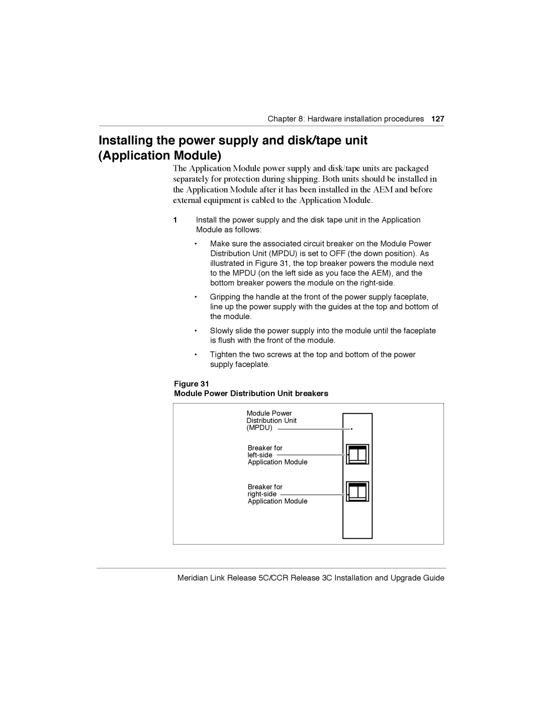
Installing the Application Module
Page
Module Power Distribution Unit breakers
Disk/tape unit
Checking the card option settings Application Module
MVME332XT ACC card jumper settings Block Jumper setting
MVME332XT ACC card switch settings Position Switch
MVME333-2 XCC card jumper settings Block Jumper setting
SP2
SP1 DTE
SP3 DTE
SP3
SP1
SP1 DCE
SP3 DCE
SP4 DTE
SP2 DTE
Page
MVME332XTS transition card serial port configuration
MVME333-2 transition card serial port configuration
MVME705B transition card serial port configuration
DTE DCE DCE DCE
MVME712AM transition card configuration
DCE DTE
SP4
MVME712A transition card configuration
MVME712M card with jumpers
NTAK02 SDI/DCH card switch settings Switch Port
Installing an NTAK02 SDI/DCH card
SDI
Esdi
Location RS-422
NTAK02 SDI/DCH card jumper and switch locations
Installing an Esdi or Msdl card
Port 1ÑSW3 Port 1ÑSW7
NT6D80 Msdl card switch settings Port 0ÑSW4 Port 0ÑSW8
Port 2ÑSW2 Port 2ÑSW6
Port 3ÑSW1 Port 3ÑSW5
NT6D80 Msdl card jumper and switch locations
Part Program socket selection Option Port no Socket number
Part Switch S2ÑAddress selection Device no Style a Style B
UA9
UB9
QPC513 Esdi card jumper and switch locations
Hardware installation procedures Standard October
IPE Module cabling
Meridian Link/CCR interface cabling
IPE Module cables
151
NT1R03BA
NT1R03AA and NT1R03BA IPE Module cables
NT1R03CA
External I/O cables
¥ NTND27AB ¥ NTAK19AA ¥ NTAK19BA
External I/O cable pinouts IPE Module
GND SCT
RTS CTS
DTR Scte
RTS CTS
GND DTR
CTS RTS
Fgnd
From Port Signal DB-50 DB-15 Name
Meridian Link/CCR interface cabling
TXD2 RXD2 RTS2
GND2
TXD4 RXD4 RTS4
DSR4 DTR4 GND6
RTS CTS DSR GRD
NT8D93A cable pinout IPE Module 25-pin Signal Pin Connector
NT8D82 cable pinout IPE Module Pin connector
RTS CTS DSR GRD
GND TXD RXD RTS CTS DSR
DSR0 RTS0 RXD0 DTR0 CTS0 TXD0
NTAK19AA cable pinout IPE Module Meridian Signal Port 0 pin
Port 1 pin
DSR1 RTS1 RXD1
DSR0 RTS0 RXD0 DTR0 DCD0 CTS0 TXD0 SG0
NTAK19BA cable pinout IPE Module Meridian Signal Port 0 pin
SCTEA1
DSR2 RTS2 RXD2 DTR2 DCD2 CTS2 TXD2 SG2
NTAK19BA cable pinout IPE Module Meridian Signal Port 2 pin
Port 3 pin
SCTEA3
SDI and ESDI/MSDL cabling Option 11 IPE Module only
IPE Module Option 11 connections Part
Method
NTAK19BA
Meridian Mail cabling IPE Module
Meridian Mail cabling IPE Module
SDI cabling Options 21Ð81 IPE Module
ESDI/MSDL cabling Options 21Ð81 IPE Module
SDI Paddle Board cabling Options 21Ð81 IPE Module only
NT7D58 cable pinout Meridian Signal AM J2
TXD RXD RTS CTS DSR
STC SCR DTR Scte
SDI/MSDL
Cabling to Meridian 1 SDI and Msdl Options 21Ð81 IPE Module
Cabling to Meridian 1 SDI and Esdi Options 21Ð81 IPE Module
Cabling to external equipment
Cabling the Option 11 IPE Module to external equipment
NT1R03D
Option 11 system IPE Module connections
NT1R03D NT1R03HF
Option 11 main cabinet connector panel
Meridian Link/CCR interface cabling
Page
External equipment External cable or reference Port
Option 11 IPE Module external connections NT1R03AA cable
Option 11 IPE Module external connections NT1R03BA cable
Console cable pinout NT1R03D Meridian Signal IPE Module
DTR GND
TXD RXD RTS CTS
Host Link cable pinout IPE Module Signal Host Connection
Txci
Risk of system interruption
Risk of equipment damage
NT8D11 backplane cable designations standard configuration
L0-1
NT8D11 backplane cable expansionÑall PE slots
NT8D11 backplane cable expansionÑfirst four PE slots only
L0-1
L6-1
Risk of hardware damage
L0-1
NT8D11 backplane cable designations rerouted for slots 0Ð3
Backplane cable rerouting for NT8D37 IPE Module
L10-1
Segment
NT8D37 backplane cable designations standard configuration
NT8D37 backplane cable expansionÑsegment
NT8D37 backplane cable expansionÑsegment
L1-3
Meridian Link/CCR interface cabling
Backplane slot Port Connector Position
Risk of hardware damage
L0-1
L14-1
Segment
Risk of hardware damage
Risk of hardware damage
Cabling the Options 21Ð81 IPE Module to external equipment
Options 21Ð81 system IPE Module connections
IPE shelf I/O panels Options 21Ð81
Left I/O panel Right I/O panel
0Ð3 1Ð4 2Ð5 3Ð6 4Ð7 5Ð8 6Ð9
Port External equipment External cable or reference
Options 21Ð81 IPE Module external connections NT1R03AA cable
Options 21Ð81 IPE Module external connections NT1R03BA cable
+12
Application Module cabling
Power cables
NT7D55AD AC/DC
Power harness cables Application Module Part number
NT7D55BM AC/DC
NT7D55AB DC NT7D55AL DC NT7D55AG
Power harness wiring diagram Application Module
Internal I/O cables
Input/output cables
Rear of Application Module
Internal I/O cabling Application Module
External I/O cables Application Module
Transition card to the Int Modem port
NT7D79BA
NT7D58CA
NT7D95AA
NT7D47EA
NT8D82AD
NT8D82AC
NTND27AB
NT7D58BB
NTND82AA
NT8D96AE
Cabling the Application Module to external equipment
Page
Page
Page
Subpanel connectors Meridian Link
Meridian Link/CCR interface cabling
Universal I/O panel Meridian Link and co-residency
Universal I/O panel CCR
Generic I/O panel Meridian Link and co-residency
Generic I/O panel CCR
MVME712A Transition card
Internal Cabling External Cabling
MVME712AM Transition card
Internal Cabling
Sub-panel
NT7D60AA MVME712AM
MVME712A Transition card Universal I/O panel
Internal Cabling
Application Module Internal Cabling
MVME712M Transition card Generic I/O panel
Application Module J8 on I/O sub-panel
Cabling to Meridian 1 SDI and Esdi Application Module
J2 on I/O sub-panel
Cabling to Meridian 1 SDI and Msdl Application Module
ESDI/MSDL cabling Application Module
System console cabling Application Module
Host computer cabling Application Module
Host port pinout Pin Signal Direction Connection
SDI cabling Application Module
NT7D61 cable pinout Meridian Signal AM J8
NT8D84AA cable pinout Pin connector Signal DB9 connector
NT7D46 cable pinouts Meridian Signal AM J8
SDI Paddle Board cabling Application Module
RD1 TD1 DTR1
CD1
DSR1 RTS1 CTS1
CD2
Internal modem cabling MVME712AM card only
NT7D71 cable pinout AM 9-pin Signal MDF RJ-11 Tip Ring
Meridian Mail cabling Application Module
Meridian Mail cabling Application Module
Adding a connection to Meridian Mail
Installing Ethernet LAN support
Ethernet backbone terminology example
IPE
Ethernet connections to IPE Module and Application Module
Page
NT7D47DA cable pinout P1 end P2 end NT7D47EA cable pinout
VT220, VT320, and VT420 terminals
Installing peripheral devices
261
Current setup values are displayed on a series of screens
Display Set-Up
VT220 Setup values Set-Up Directory
General Set-Up
Communications Set-Up
Tab Set-Up Screen
VT320 Setup values Set-Up Directory
Display Set-Up
VT420 Setup values
Personal computer running Reflection 4+
Downloading the Reflection 4+ configuration file
MTE8 window appears
Meridian Terminal Emulator MTE
Epson
Dot-matrix printer switch settings
Form Lines Robust XON DTR Polarity
LaserJet series II printer switch settings
Copies Auto OFF Font Source Serial Font Number
LaserJet series III printer switch settings
Paper Letter Baud Rate
RET Dark Timeout
LaserJet series IV printer switch settings
MP Tray Class Serial
Lock None Pacing XON/XOFF CLR Warn Baud Rate
DeskJet and DeskJet 500 printer switch settings
DeskJet and DeskJet 500 printer switch settings
DCE and DTE connections
Peripheral device cabling interface
273
Straight RS-232 cable
Null modem RS-232 cable
Connecting the A/B switchbox
Using an A/B switchbox to share system consoles
ÒConsole LoginÓ prompt appears
Using the A/B switchbox to switch applications
Limited-distance modem
Modems
USRobotics Sportster modem
Gandalf LDS 120E limited-distance modem
VME
YES TALK/DATA MR/RI TR HS MC RD TD
Dial-up modem
2440
Configuring the UDS 2440 modem for remote diagnostics
RESET? FACTORY? YES Factory 0?
Offline DIAL? Test Auto ANS? Data OPTS? OPTIONS? YES RESET?
DTR OPTS? DSR OPTS? YES DSR FORCED?
OFFLINE? DIAL? TEST? Auto ANS? YES Auto ANS E? RINGS?
CD OPTS? CTS OPTS?
DSR OPTS? CD OPTS? YES CD FORCED?
Offline
Connect the modem to a workstation and apply power to both
Ven-Tel 2400 modemÑopening the modem
Ven-Tel 2400 modem SW2 switch settings
Ven-Tel 2400 modemÑswitch locations
Ven-Tel 2400 Plus II modemÑopening the modem
Ven-Tel 2400 Plus II modem switch settings
Ven-Tel 9600 Plus modemÑopening the modem
Ven-Tel 2400 Plus II modemÑswitch locations
Dial-up modemÑVen-Tel 9600 Plus modem SW2 switch settings
Ven-Tel 9600 Plus modemÑswitch locations and settings
Conventional notation
Meridian 1 configuration for Meridian Link/CCR
293
Presents some of these conventions
Summary of Meridian 1 configuration
Configuration overview
Configuring the VSID, HSID, and AML prompts
Meridian 1 configuration for Meridian Link/CCR
Meridian 1 configuration for Meridian Link/CCR
Options 21Ð81 Esdi configuration
Configure Esdi port X11 Release
BPS
Dupx Full
Clok INT
Iadr
Intl
Secu YES
Mcnt
Conf DIR
LD 48ÑLink Diagnostic Command Comment
Enable Esdi port X81 phase 7 or X11 Release
Following commands may be used for diagnostic purposes
ENL MSGI/MSGO
Flsh
DIS MSGI/MSGO
Stat MON
ENL PACI/PACO
Enit
Dsxt
Dsit
Option 11 Esdi configuration
Configure Esdi or Msdl port X11 Release 18 or later
LD 17ÑConfigure Esdi port Option Prompt Response Comment
PWD Parm
Lthr ENL Adan
Cequ Ovly VAS NEW
Intl Mcnt Conf DIR
Atrn Alarm
REQ CHG, END
Ctyp MSDL, Esdi
Option 21Ð81 Esdi or Msdl configuration
Dnum
DES
Rxmt
Lthr
CRC
Orur
VAS NEW
Abor
Vasid
Vsid Csqi
Either change the configuration
Enable Esdi or Msdl port X11 Release 18 or later
MSGI/MSGO Only those messages specified xx=link Msg msg
TBL1
Stat AML
TBL2
TBL3
PWD2 Isdn Parm Cequ Ovly Iotb
Configure SDI port for conshare X11 Release
Esdi User MTC SCH
VAS Vsid Dlop CMS Secu Atrn
Mscl
Configure SDI port for conshare X11 Release 18 or later
LD 37ÑInput/output diagnostic Command Comment
Enable SDI port
Stat
Stat TTY
LD 15ÑEnable Dnis Prompt Response Comment
Configuring Dnis to use auto-terminating trunks
LD 15ÑCustomer data block
LD 16ÑRoute data block
LD 16ÑTrunk route administration Prompt Response Comment
Ndgt
Dnis YES
Icog
Acod
LD 14ÑTrunk data block
LD 14ÑConfigure auto-terminating DN Prompt Response Comment
Tkid
Supn NO, YES
LD 15ÑACD routing by Dnis number Prompt Response Comment
Configuring Dnis to use Incoming Digit Conversion
IDC YES
Dcno
Type IDC
Idgt
End of modifying for this translation table
REQ NEW, END
REQ NEW
LD 49ÑPartial digit conversion Prompt Response Comment
Configure devices for status change host notification
Meridian 1 configuration for Meridian Link/CCR
Meridian 1 configuration for Meridian Link/CCR
LD 15ÑDefine status message groups Prompt Response Comment
Define status message groups
Default values are in group 0
Define ACD groups and agents
Assign telephones to status message groups Meridian Link
LD 23ÑBuild ACD groups Prompt Response Comment
Either build another ACD group or exit
Define ACD telephones as AST
Aacd YES
PRI
FTR
KLS
DES ACD Cust
KEY MSB
KEY ACD Xxxxxxx = ACD DN Yyyy
KEY NRD
KEY TRN
AST YES
Define non-ACD telephones as AST
Cden
KEY RLS
KEY SCR Xxxx = AST DN TRN
LD 23ÑDefine the default ACD DN Prompt Response Comment
Configure ACD DNs
MWC AST
Sdnb Bscw Isap
IVR YES
MWC Dsac Maxp
Trdn
LD 23ÑDefine CDNs Prompt Response Comment
Configure Control DNs CCR
Murt
Froa YES, no
Dfdn
Ceil
Ovth
Byth
Acnt
LD 17ÑSet up Phantom Loops Prompt Response Comment
Configuring a Phantom Loop
Type Supl
Configuring a Phantom Superloop
LD 10ÑCreating a Phantom Set Prompt Response Comment
Creating a Phantom Set
CLS Dndd
CLS NDD
Itna NO, YES
Dgrp
LD 23ÑConfiguring Dual VAS ID Prompt Response Comment
Configuring Dual VAS ID
MWC YES, no IMS CMS IMA Ivms EES Vsid
Isap YES, no
Traffic statistics
LD 2ÑTraffic statistics Command Comment
Prompt Response
355
Meridian Mail configuration
Meridian Mail configuration
Meridian Mail call processing
Meridian Mail call processing
Creating a Meridian Mail ACD queue
Configuring Meridian 1 for Meridian Mail
MWC YES
Alog YES Sdnb Bscw Rgai Fcth Crqs
IMS YES CMS IMA Ivms Vsid
Defining virtual agent DNs for voice channels
FDN Tgar LDN Ncos Rnpg SSU Xlst CLS VMA
Type SL1
Hunt
KEY SCN
LHK TEN Spid AST Iapg PRI Lang KEY ACD
A06 Assign an A06 6-party conference key where = key number
Procedure to add the Meridian Mail ACD DN to the Vsdn Table
ACC
Example of Meridian Mail Voice Service DN Vsdn Table Class
Defining voice channels in the Channel Allocation Table CAT
CSL
Procedure to add channels to Meridian Mail
Defining a new mailbox for the application
Procedure to add a new mailbox to the Meridian Mail system
Meridian Mail Add Local Voice User screen
Meridian Mail configuration Standard October
371
Software installation, upgrade, and update procedures
Software installation, upgrade, and update procedures
Software installation and upgrade paths From Covered
CCR
Software upgrade paths From Covered in section
Software installation, upgrade, and update procedures
Software installation, upgrade, and update procedures
Software installation, upgrade, and update procedures
To upgrade Meridian Link from Release 4 to Release 5C
To upgrade Meridian Link from Release 4 to Co-residency
To upgrade Meridian Link from Release 4B to Release 5C
Software installation, upgrade, and update procedures
To update Meridian Link from Release 5 to Co-residency
To update Meridian Link from Release 5 to Release 5C
Software installation, upgrade, and update procedures
To update CCR from Release 3 to Co-residency
To update CCR from Release 3 to Release 3C
To update CCR from Release 3B to Co-residency
To update CCR Release 3B to Release 3C
To install or reinstall the software from tape
Activating or de-activating a Meridian Link or CCR feature
Risk of potential data loss
Tape prompt
Procedure 1 Application configuration and start-up
Meridian 1 ID prompt
Keycode group 2 or Q or q to quit
Meridian Link protocol prompt
List verification prompt
Subnet mask prompt
CCR customer number prompt
Procedure 1 Application configuration and start-up
Software installation, upgrade, and update procedures
Module name prompt
Reenter prompt
Reboot prompt
Change password prompts Maint chgpasswd
Install command prompt
Procedure 2 Start the update process
Drive selection menu
Software installation, upgrade, and update procedures
Risk of accidental overwriting of data on tape
Procedure 3 Load application software from tape
Write-protecting the cartridge tape
Inserting cassette tape in tape drive
Procedure 3 Load application software from tape
Series of messages appear on the screen
Keycode prompt
Meridian Link protocol prompt
Procedure 3 Load application software from tape
System lists the application or applications installed
CCR customer number prompt
Software install messages
Module address prompt
System clears and the following messages appear
Reboot messages
Remove the application tape from the cassette tape drive
Machine Management
Powerdown notification message screen
System is Being Shutdown NOW
Shutdown message screen
System restart messages MVME147 card
Results of disk/tape controller scan
Start-up interrupt menu
Autoboot enable prompts
Environment prompts for firmware revision
Environment prompts appear
Either case, the start-up interrupt menu appears
BOS installation tape Tape drive
Example 0314163098 or
System start-up messages
BOS software management menu
Disk drive number prompt
BOS installation, phase
CDC ST1126N
Disk types used Select this number
CDC ST1201N
Same disk drive prompt
Format disk drive prompt
Slice number prompt
Disk-slicing table for 172-Mbyte disk drive
Disk-slicing table for 104-Mbyte disk drive
Install Tars prompt
Install Olmp prompt
Disk-slicing table for 240-Mbyte disk drive
Software installation summary
Verify installation prompt
System responds with ÒRe-enter new password.Ó
Reset the System
Start-up interrupt menu appears
System restart messages IPE Module or MVME167 card
Environment prompts IPE Module
Return
At the Ò167-DiagÓ prompt, type env and press Return
Additional prompts MVME167 card
Cr Type a period and press Return
Software installation, upgrade, and update procedures
BOS installation tape
Controller prompt
Alternate boot device prompt
Drive prompt
File prompt
Seagate
Example 0314163098 or
System response is ÒSelected the ÔMVME167Õ controller type.Ó
List of disk drive types
Format disk drive prompt
Slice number prompt
Disk-slicing table for 172-Mbyte disk drive
Disk-slicing table for 240-Mbyte disk drive
Install Tars prompt
Software installation, upgrade, and update procedures
System responds with ÒRe-enter new passwordÓ
Reset the System
MVME147 Application Module start-up messages
Procedure 7 Reboot and go through setup
IPE Module or MVME167 Application Module start-up messages
System autoboot messages
Procedure 7 Reboot and go through setup
Root password is reset once the application is installed
Port configuration messages shown in appear on your screen
Portconfig warning
Procedure 7 Reboot and go through setup Portconfig messages
Time zone menu
Time zone prompt
DST prompt
Additional time zone menu
Date and time change prompt
Day prompt
Month prompt
Year prompt
Hour prompt
Time change confirmation
Date and time set prompt
UserÕs name prompt
Change system name prompt
Setup end message
System name prompt
System administration menu
Procedure 8 Load the application software from tape
Software Management
Insert medium prompt
IPE Module drive Application Module drive
Series of messages appears on the screen
Keycode prompt
Procedure 8 Load the application software from tape
IP address prompt
System lists the application or applications installed
CCR customer number prompt
Software install messages
Module address prompt
System clears and the messages in appear
Remove the application tape from the cassette tape drive
Stop applications prompt
Rstdata prompt
Restore link control files prompt
Please enter ÔyÕ to do restore, or ÔnÕ to quit y,n
Software installation, upgrade, and update procedures
File verification messages
Procedure 10 Verify the installation
Backdata messages
Procedure 11 Back up configuration files and data files
Software installation, upgrade, and update procedures
Page
Default configuration
Link configuration
Link 0ÑApplication Module Link
479
LOC LIC Ð1 HOC HIC Ð1
Link 1ÑX.25 protocol Meridian Link
Link 2ÑMeridian Mail Link optional for Meridian Link
Link 1ÑTCP/IP host link protocol Meridian Link
Changing your configuration
Meridian Link only
Procedure 12 Verifying the link status
Link 0 parameters
Procedure 13 Changing AML link 0 parameters
Hdlc
Change link parameters
Procedure 13 Changing AML link 0 parameters
Lapb
=HDLC
DDN USA
Link configuration
End Ñ
First parameter appears, along with the current value
X25, Hdlc
Link configuration
Only parameters
DTE/DCE
HOC HIC
LOC LIC
End Ñ
LAN
Default link configuration is displayed, as shown in Table
Async
Procedure 15 Changing Meridian Mail Link link 2 parameters
Save link parameters
Procedure 16 Replacing the default configuration file
Save link file
Procedure 17 Creating a configuration file
Procedure 17 Creating a configuration file
Entry 1 X25 /usr/mlusr/conf/filename.datafile cr
Procedure 17 Creating a configuration file Change linkctl
503
Additional application configuration
Additional application configuration
Bootconfig prompt
Procedure 18 Turn off auto-start
Auto-start disabled message
Customer number prompts
Procedure 19 Change the Meridian 1 customer number
Commit prompt
Backup schedule prompt
Procedure 20 Schedule regular backups
Backup time prompts
Reoccurring backup prompt
Procedure 20 Schedule regular backups Backup day prompts
Backup tape notice
Langconfig options prompt
Procedure 21 Change the default system languages
Default language prompt
Language options confirmation prompt
Port configuration menu
Procedure 22 Configure terminal ports
Port number prompt
Port configuration confirmation
Procedure 22 Configuring terminal ports Port state prompt
Baud rate prompt
Procedure 23 Configure printer ports
Procedure 23 Configuring printer ports Port state prompt
Printer name prompt
Printer enabled message
Procedure 23 Configuring printer ports
Printer model menu
517
Hardware upgrade
Powerdown messages
Procedure 24 Software powerdown
System is Being Shut Down NOW
Procedure 24 Software powerdown Shutdown message screen
Complete Procedure 24 Software powerdown
Procedure 25 Hardware powerdown
System reboots into the ÒConsole LoginÓ prompt
Hardware upgrade
Page
Hardware upgrade
Page
Procedure 29 Installing the MVME332XT or MVME332XTS ACC card
Meridian Link/CCR
Acceptance testing
527
CCR User Guide
Meridian Mail
Using Edit Voice to create voice segment files
Creating a header file
Recording and trimming voice segments
Example of customer account balance query
Using Edit Voice for the first time
Example of voice segment file
Example of Play Voice session
Hardware and software requirements
Single Terminal Access
533
Before you begin
STA for Meridian Link/CCR on an IPE Module
Msdl
STA for Meridian Link/CCR on an Application Module
Msdl
Setting up STA
LD 17ÑConfigure Msdl port Prompt Response Comment
SDI DIS Port
Stat Msdl
TTY
Admin
Lang ENG
Additional
Stat STA
Stat Enabled TGT Enabled
Stat Msdl Msdl 11 Enbl STA
STA Port
STA Main Menu
Port configuration Prompt Response
Single Terminal Access Standard October
545
Ordering
NT7D46AB
NT6D51AA
NT7D46AD
NT7D46AF
NT1R02BA
NT1R02AA
NT8D93AW
NT8D93AJ
NTAK19AA
NTAK19BA
NT1R03EF
NT1R03EB
NT1R03EP
NT1R03EV
Hours
Component failure rates
Failures
SMM167 SBC card
Ordering Standard October
Application Equipment Module AEM
List of terms
Application Module AM
Application Module Link AML
Attendant
Command and Status Link CSL
Automatic Call Distribution ACD
Automatic Call Distribution Directory Number ACD DN
Customer Controlled Routing CCR
Directory Number Identification Service Dnis
Direct Inward Dialing did
Directory number DN
Enhanced Serial Data Interface Esdi
Module Power Distribution Unit Mpdu
Intelligent Peripheral Equipment IPE Module
Interactive Voice Response IVR
Overlay
Operations, Administration and Maintenance OA&M
Private branch exchange PBX
Profile
SDI port
Stand-alone System Interactive Diagnostics Ssid
Terminal number TN
Trunk
559
Index
AST
Index
Index
Index
Index
Index
IDC
Lapb
Index
Jumper settings and cable connections
Index
PBX
Index
SDI
Definition 558 description 16 standalone system
Index
Index
Meridian Link Customer Controlled Routing
Installation and Upgrade Guide