1152700 • Issue 1 • February 2001 • Section 2 Operation and Maintenance
Page 2 of 4
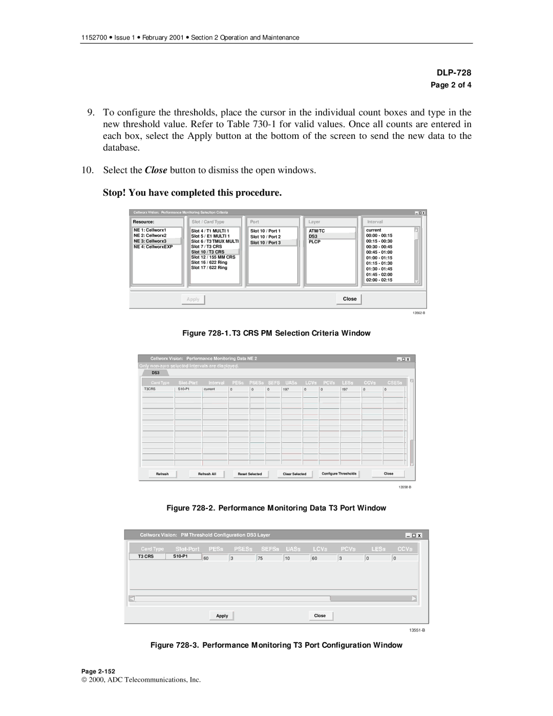
9.To configure the thresholds, place the cursor in the individual count boxes and type in the new threshold value. Refer to Table
10.Select the Close button to dismiss the open windows.
Stop! You have completed this procedure.
Cellworx Vision: Performance Monitoring Selection Criteria |
|
| X |
Resource:
NE 1: Cellworx1
NE 2: Cellworx2
NE 3: Cellworx3
NE 4: CellworxEXP
Slot / Card Type
Slot 4 / T1 MULTI 1 Slot 5 / E1 MULTI 1 Slot 6 / T3 TMUX MULTI Slot 7 / T3 CRS
Slot 10 / T3 CRS
Slot 12 / 155 MM CRS Slot 16 / 622 Ring Slot 17 / 622 Ring
Port
Slot 10 / Port 1
Slot 10 / Port 2
![]() Slot 10 / Port 3
Slot 10 / Port 3
Layer
ATM/TC
DS3
PLCP
Interval
current 00:00 - 00:15 00:15 - 00:30 00:30 - 00:45 00:45 - 01:00 01:00 - 01:15 01:15 - 01:30 01:30 - 01:45 01:45 - 02:00 02:00 - 02:15
Apply |
Close |
Figure 728-1.T3 CRS PM Selection Criteria Window
Cellworx Vision: Performance Monitoring Data NE 2 |
|
| X |
|
Only
DS3
Card Type
T3CRS
Interval
current
PESs PSESs SEFS UASs
0 | 0 | 0 | 197 |
|
|
|
|
LCVs PCVs
0 | 0 |
|
|
LESs
197
CCVs
0
CSESs
0
Refresh | Refresh All |
Reset Selected
Clear Selected
Configure Thresholds
Close
Figure 728-2. Performance Monitoring Data T3 Port Window
Cellworx Vision: PM Threshold Configuration DS3 Layer |
|
|
|
| X | ||||
Card Type | PESs | PSESs | SEFSs | UASs | LCVs | PCVs | LESs | CCVs | |
T3 CRS | 60 | 3 | 75 | 10 | 60 | 3 | 0 | 0 | |
|
| ||||||||
|
| Apply |
|
|
| Close |
|
|
|
|
|
|
|
|
|
|
|
| |
Figure 728-3. Performance Monitoring T3 Port Configuration Window
Page
2000, ADC Telecommunications, Inc.