1152700 • Issue 1 • February 2001 • Section 2 Operation and Maintenance
Page 5 of 5
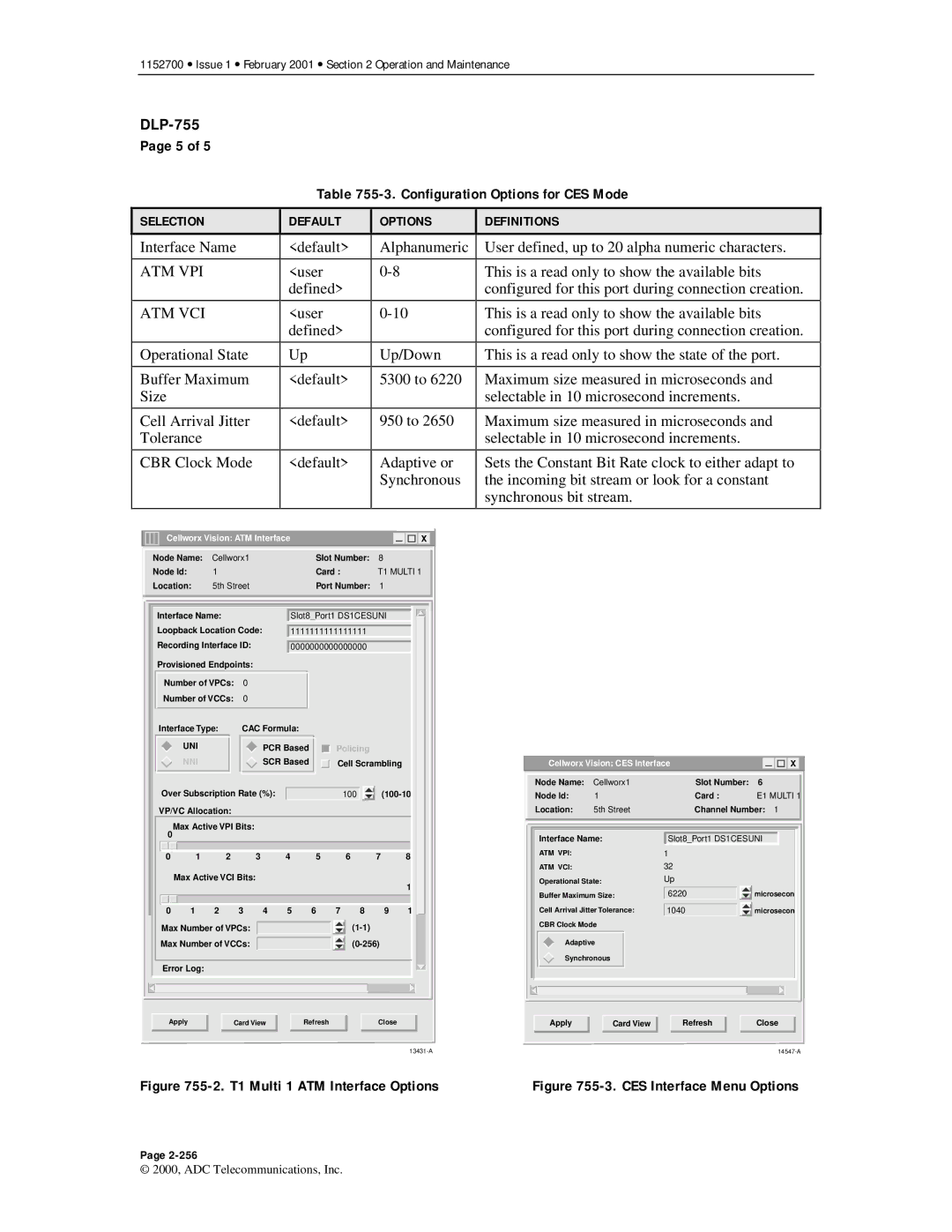
SELECTION
Table
| DEFAULT |
| OPTIONS |
| DEFINITIONS |
|
|
|
|
|
|
|
|
Interface Name
ATM VPI
ATM VCI
Operational State
Buffer Maximum Size
Cell Arrival Jitter Tolerance
CBR Clock Mode
<default>
<user
defined>
<user
defined>
Up
<default>
<default>
<default>
Alphanumeric
Up/Down
5300 to 6220
950 to 2650
Adaptive or Synchronous
User defined, up to 20 alpha numeric characters.
This is a read only to show the available bits configured for this port during connection creation.
This is a read only to show the available bits configured for this port during connection creation.
This is a read only to show the state of the port.
Maximum size measured in microseconds and selectable in 10 microsecond increments.
Maximum size measured in microseconds and selectable in 10 microsecond increments.
Sets the Constant Bit Rate clock to either adapt to the incoming bit stream or look for a constant synchronous bit stream.
Cellworx Vision: ATM Interface |
|
| X | ||
Node Name: | Cellworx1 |
| Slot Number: | 8 | |
Node Id: | 1 |
|
| Card : | T1 MULTI 1 |
Location: | 5th Street |
| Port Number: | 1 | |
Interface Name: |
| Slot8_Port1 DS1CESUNI | |||
Loopback Location Code: | 1111111111111111 |
| |||
Recording Interface ID: | 0000000000000000 |
| |||
Provisioned Endpoints: |
|
|
| ||
Number of VPCs: | 0 |
|
|
| |
Number of VCCs: | 0 |
|
|
| |
Interface Type: | CAC Formula: |
|
| ||
UNI |
| PCR Based | Policing |
| |
NNI |
| SCR Based | Cell Scrambling | ||
Over Subscription Rate (%): |
| 100 | |||
VP/VC Allocation: |
|
|
|
| |
Max Active VPI Bits: |
|
|
| ||
| Cellworx Vision: CES Interface |
|
|
|
| X |
| |
|
|
|
|
|
|
|
|
|
|
|
|
|
|
|
|
|
|
| Node Name: | Cellworx1 | Slot Number: | 6 |
|
|
|
|
| Node Id: | 1 | Card : | E1 MULTI 1 |
| |||
| Location: | 5th Street | Channel Number: 1 |
| ||||
|
|
|
|
|
|
|
|
|
0 |
|
|
|
|
|
|
|
|
|
|
|
|
|
|
| ||
|
|
|
|
|
|
|
|
|
|
|
|
|
|
|
|
|
|
| 0 | 1 |
| 2 | 3 | 4 | 5 | 6 | 7 |
| 8 |
|
| ||||
|
|
| Max Active VCI Bits: |
|
|
|
|
|
|
|
|
| 1 |
|
| ||
|
|
|
|
|
|
|
|
|
|
|
|
|
|
|
|
| |
|
|
|
|
|
|
|
|
|
|
|
|
|
|
|
|
| |
|
|
|
|
|
|
|
|
|
|
|
|
|
|
|
|
|
|
0 | 1 | 2 | 3 | 4 | 5 | 6 | 7 |
| 8 |
| 9 | 1 | |||||
| Max Number of VPCs: |
|
|
|
|
|
|
|
|
|
| ||||||
|
|
|
|
|
|
|
|
|
|
| |||||||
| Max Number of VCCs: |
|
|
|
|
|
|
|
|
|
|
| |||||
|
|
|
|
|
|
|
|
|
|
| |||||||
|
|
|
|
|
|
|
|
|
|
|
|
|
|
|
|
|
|
| Error Log: |
|
|
|
|
|
|
|
|
|
|
|
|
|
| ||
|
|
|
|
|
|
|
|
|
|
|
|
|
|
|
|
|
|
|
|
|
|
|
|
|
|
|
|
|
|
|
|
|
|
|
|
Interface Name:
ATM VPI:
ATM VCI:
Operational State:
Buffer Maximum Size:
Cell Arrival Jitter Tolerance:
CBR Clock Mode
Adaptive
Synchronous
![]() Slot8_Port1 DS1CESUNI 1
Slot8_Port1 DS1CESUNI 1
32 Up
6220 | microsecon |
1040 |
|
| microsecon |
|
|
|
|
| Apply |
| Card View |
| Refresh |
| Close |
|
|
|
|
|
|
|
|
|
|
|
|
|
|
|
|
| ||
Apply | Card View | Refresh | Close |
Figure | Figure |
Page
© 2000, ADC Telecommunications, Inc.