1152700 • Issue 1 • February 2001 • Section 2 Operation and Maintenance
Page 2 of 5
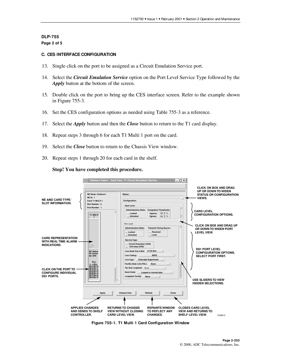
C. CES INTERFACE CONFIGURATION
13.Single click on the port to be assigned as a Circuit Emulation Service port.
14.Select the Circuit Emulation Service option on the Port Level Service Type followed by the Apply button at the bottom of the screen.
15.Double click on the port to bring up the CES interface screen. Refer to the example shown in Figure
16.Set the CES configuration options as needed using Table
17.Select the Apply button and then the Close button to return to the T1 card display.
18.Repeat steps 3 through 6 for each T1 Multi 1 port on the card.
19.Select the Close button to return to the Chassis View window.
20.Repeat steps 1 through 20 for each card in the shelf.
Stop! You have completed this procedure.
NE AND CARD TYPE/ SLOT INFORMATION.
CARD REPRESENTATION WITH REAL TIME ALARM INDICATIONS.
CLICK ON THE PORT TO CONFIGURE INDIVIDUAL DS1 PORTS.
Cellworx Vision: | Card View - T1 Circuit Emulation Service |
| X | |||||
NE Name: Cellworx1 | Status: |
|
|
|
|
|
| |
NE Id: 1 |
|
|
|
|
|
|
|
|
Card: T1 MULTI 1 | Configuration: |
|
|
|
|
|
| |
Slot Number: 8 | Card Level |
|
|
|
|
|
| |
Port Number: 1 |
|
|
|
|
|
| ||
|
|
|
|
|
|
| ||
|
| Administrative State: | Congestion Thresholds: | |||||
T1 MULTI | Locked |
|
|
| Ingress: | 80 | % | |
Unlocked |
|
|
| Egress: | 80 | % | ||
1 |
|
|
|
| ||||
|
|
|
|
|
|
|
| |
|
| Port Level |
|
|
|
|
|
|
|
| Administrative State: |
| Transmit Timing Source: | ||||
|
| Locked |
|
|
| Received |
| |
|
| Unlocked |
|
|
| Local |
|
|
|
| Service Type: |
|
|
|
|
|
|
|
| Circuit Emulation (CES) |
|
| ||||
ADC |
| Cell relay (CRS) |
|
|
|
|
| |
Status | Line Build Out (LBO): |
|
|
| ||||
Active | Line Coding: |
|
|
| B8ZS |
|
| |
APS |
|
|
|
|
| |||
|
| Line Type: | Extended Superframe |
|
| |||
Port |
| Facility Data Link (FDL): | None |
|
| |||
1 | 9 |
|
| |||||
2 | 10 | Far End Loopback: | None |
|
| |||
3 | 11 |
|
| |||||
4 | 12 |
|
|
|
|
|
|
|
5 | 13 | Send Code: | Looped or normal data |
| ||||
6 | 14 |
|
|
|
|
|
|
|
7 | 15 | Loopback Config: |
| None |
|
| ||
8 | 16 |
|
|
| ||||
|
|
|
|
|
|
| ||
| Apply | Chassis View |
|
| Refresh |
| Close | |
CLICK ON BOX AND DRAG UP OR DOWN TO WIDEN STATUS OR CONFIGURATION VIEWS.
CARD LEVEL CONFIGURATION OPTIONS.
CLICK ON BOX AND DRAG UP OR DOWN TO WIDEN PORT LEVEL VIEW.
DS1 PORT LEVEL CONFIGURATION OPTIONS. SELECT PORT FIRST.
USE SLIDERS TO VIEW
HIDDEN SELECTIONS.
APPLIES CHANGES | RETURNS TO CHASSIS | REPAINTS WINDOW | CLOSES CARD LEVEL |
|
AND SENDS TO SHELF | VIEW WITHOUT CLOSING | TO REFLECT ANY | VIEW AND RETURNS TO |
|
CONTROLLER. | CARD LEVEL VIEW. | CHANGES. | SHELF LEVEL VIEW. |
Figure 755-1. T1 Multi 1 Card Configuration Window
Page
© 2000, ADC Telecommunications, Inc.