1152700 • Issue 1 • February 2001 • Operation and Maintenance
DLP-785
Page 7 of 7
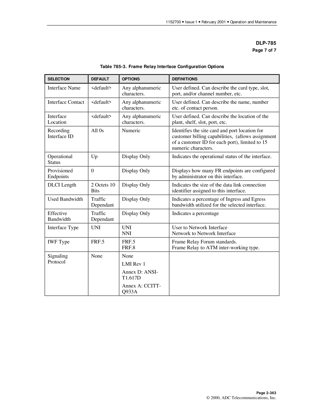
Table 785-3. Frame Relay Interface Configuration Options
SELECTION
Interface Name
Interface Contact
Interface
Location
Recording
Interface ID
Operational
Status
Provisioned
Endpoints
DLCI Length
Used Bandwidth
Effective
Bandwidth
Interface Type
IWF Type
Signaling
Protocol
DEFAULT
<default>
<default>
<default>
All 0s
Up
0
2 Octets 10 Bits
Traffic Dependant
Traffic Dependant
UNI
FRF.5
None
OPTIONS
Any alphanumeric characters.
Any alphanumeric characters.
Any alphanumeric characters.
Numeric
Display Only
Display Only
Display Only
Display Only
Display Only
UNI
NNI
FRF.5
FRF.8
None
LMI Rev 1
Annex D: ANSI- T1.617D
Annex A: CCITT- Q933A
DEFINITIONS
User defined. Can describe the card type, slot, port, and/or channel number, etc.
User defined. Can describe the name, number etc. of contact person.
User defined. Can describe the location of the plant, shelf, slot, port, etc.
Identifies the site card and port location for customer billing capabilities, (allows assignment of a customer ID for each port), limited to 15 numeric characters.
Indicates the operational status of the interface.
Displays how many FR endpoints are configured by administrator on this interface.
Indicates the size of the data link connection identifier assigned to this interface.
Indicates a percentage of Ingress and Egress bandwidth utilized for the selected interface.
Indicates a percentage
User to Network Interface
Network to Network Interface
Frame Relay Forum standards.
Frame Relay to ATM
Page
© 2000, ADC Telecommunications, Inc.