1152700 • Issue 1 • February 2001 • Operation and Maintenance
Page 2 of 10
4.Following the example shown in Figure
•FR-ATM VC
•FR-FR
5.Using the left mouse button, select the desired NE, Slot/Card Type, and Network Interface/Interface Type for the originating and destination endpoints. Click on Next>> using the left mouse button.
6.For
7.On the upper FR section, select a Data Link Connection Identifier (DLCI) under the heading DLCI/NE/Rate using the left mouse button. DLCIs that are already in use will not be selectable. The NE and Rate (Kbps) fields being visible to the user indicate these are in use already. If needed, use the scroll bar to display the available DLCIs not displayed in the window.
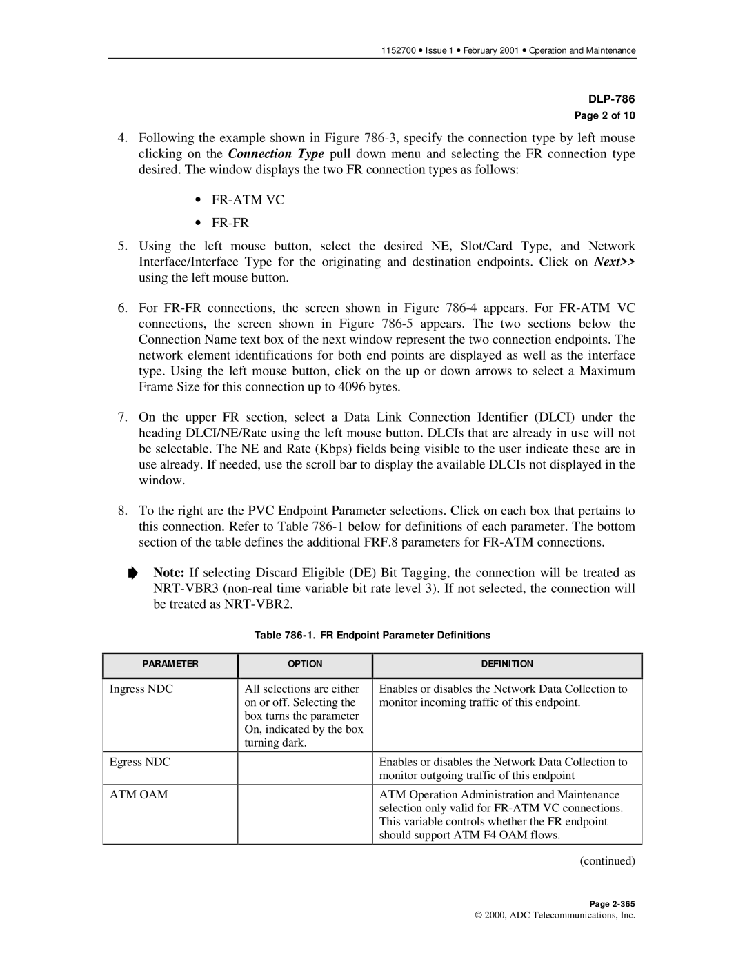
8.To the right are the PVC Endpoint Parameter selections. Click on each box that pertains to this connection. Refer to Table
Note: If selecting Discard Eligible (DE) Bit Tagging, the connection will be treated as
PARAMETER
Table 786-1. FR Endpoint Parameter Definitions
| OPTION |
| DEFINITION |
|
|
|
|
|
|
|
|
Ingress NDC
Egress NDC
ATM OAM
All selections are either on or off. Selecting the box turns the parameter On, indicated by the box turning dark.
Enables or disables the Network Data Collection to monitor incoming traffic of this endpoint.
Enables or disables the Network Data Collection to monitor outgoing traffic of this endpoint
ATM Operation Administration and Maintenance selection only valid for
(continued)
Page
© 2000, ADC Telecommunications, Inc.