1152700 • Issue 1 • February 2001 • Section 2 Operations and Maintenance
Page 1 of 3
CARD AND SHELF RESET
Summary: This procedure instructs the operator in the steps required to perform software reset on the shelf or various cards within the Cellworx STN shelf. Cards can be individually reset or a group of cards can be selected at one time to be reset. It is assumed that the user has gained access to the system and launched the GUI before attempting this procedure.
1.Select the node to have the reset performed on it by double clicking on the icon shown on the main GUI screen.
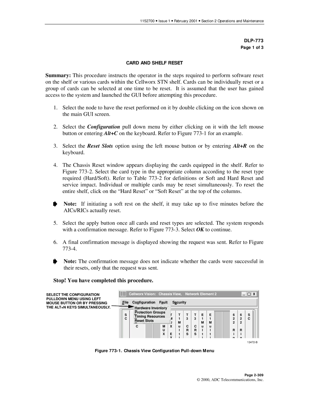
2.Select the Configuration pull down menu by either clicking on it with the left mouse button or entering Alt+C on the keyboard. Refer to Figure
3.Select the Reset Slots option using the left mouse button or by entering Alt+R on the keyboard.
4.The Chassis Reset window appears displaying the cards equipped in the shelf. Refer to Figure
Note: If initiating a soft rest on the shelf, it may take up to five minutes before the AICs/RICs actually reset.
5.Select the apply button once all cards and reset types are selected. The system responds with a confirmation message. Refer to Figure
6.A final confirmation message is displayed showing the request was sent. Refer to Figure
Note: The confirmation message does not indicate whether the cards were successful in their resets, only that the request was sent.
Stop! You have completed this procedure.
SELECT THE CONFIGURATION PULLDOWN MENU USING LEFT MOUSE BUTTON OR BY PRESSING THE ALT+N KEYS SIMULTANEOUSLY.
| Cellworx Vision: Chassis View, Network Element 2 |
|
| X |
|
|
|
|
|
|
|
File | Configuration | Fault |
| Security |
|
|
|
|
|
|
|
| Hardware Inventory |
|
|
|
|
|
|
|
|
| |
S | Protection Groups | T | T | T | T E E | 6 | 6 | S | |||
N | T | ||||||||||
C | Timing Resources | M | 1 | 3 | 3 1 | 1 | 2 | 2 | C | ||
M | 3 | ||||||||||
| Reset Slots |
| U | M |
|
| M | M | 2 | 2 |
|
|
|
|
|
|
| ||||||
| C | M | X | u | C | C | u | u |
|
|
|
|
| U |
| l | R | R | l | l | R | R |
|
|
| X | E | t | S | S | t | t | i | i |
|
|
|
| X | i |
|
| i | i | n | n |
|
Figure 773-1. Chassis View Configuration Pull-down Menu
Page
© 2000, ADC Telecommunications, Inc.
