1152700 • Issue 1 • February 2001 • Operation and Maintenance
DLP-785
Page 6 of 7
Table 785-2. FT1 FRS Configuration Options, Continued
SELECTION
Loopback
Far End Loopback
DEFAULT
None
None
OPTIONS
None
Facility Line
Terminal
Facility
Payload
None
Line
Payload
Reset
DEFINITIONS
No Loopback selected.
Loops frames back out to EIM after assigning overhead and buffering.
Loops ATM cells back to Cellbus.
Loops the payload back to customer interfacing equipment before assigning overhead and buffering.
No loopback is requested.
Tells the far end to loop the line back.
Tells the far end to loop the payload after line data is extracted.
Tells the far end to stop the loopback.
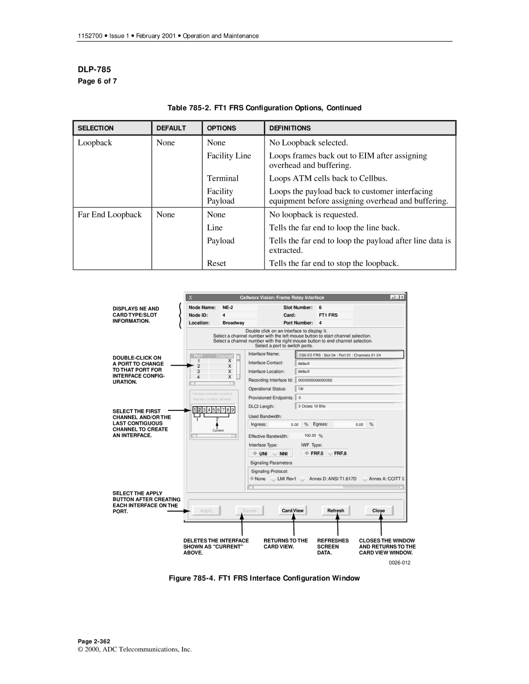
DISPLAYS NE AND CARD TYPE/SLOT INFORMATION.
SELECT THE FIRST CHANNEL AND/OR THE LAST CONTIGUOUS CHANNEL TO CREATE AN INTERFACE.
| Cellworx Vision: Frame Relay Interface |
|
| X | |||
|
|
|
|
|
|
|
|
|
|
|
|
|
|
|
|
Node Name: | Slot Number: | 6 |
|
|
|
| |
|
|
|
|
|
|
|
|
Node ID: | 4 | Card: | FT1 FRS |
|
|
|
|
|
|
|
|
|
|
|
|
Location: | Broadway | Port Number: | 4 |
|
|
|
|
Double click on an interface to display it.
Select a channel number with the left mouse button to start channel selection.
Select a channel number with the right mouse button to end channel selection.
Select a port to switch ports.
Port | Channel | Interface Name: |
| |||||
|
|
| ||||||
1 | X | Interface Contact: | default |
|
|
| ||
2 | X |
|
|
| ||||
|
|
|
|
|
|
| ||
3 | X | Interface Location: | default |
|
|
| ||
4 | X | Recording Interface Id: | 0000000000000000 |
|
| |||
|
|
|
| |||||
|
| Operational Status: | Up |
|
|
| ||
Interface selection enabled | Provisioned Endpoints: |
| 0 |
|
|
| ||
Interface creation allowed |
|
|
|
| ||||
1 2 3 4 5 6 7 8 9 | DLCI Length: |
|
| 2 Octets 10 Bits |
|
| ||
|
|
|
|
|
|
| ||
1 | 2 | Used Bandwidth: |
|
|
|
|
| |
Ingress: |
|
| % | Egress: |
| % | ||
|
| 0.00 | 0.00 | |||||
| Current |
|
|
|
|
|
|
|
|
| Effective Bandwidth: |
| 100.00 % |
|
| ||
|
| Interface Type: |
|
| IWF Type: |
|
| |
|
| UNI | NNI |
|
| FRF.5 | FRF.8 |
|
|
| Signaling Parameters |
|
|
|
|
| |
|
| Signaling Protocol: |
|
|
|
|
| |
|
| None | LMI Rev1 |
| Annex D: ANSI T1.617D | Annex A: CCITT Q | ||
SELECT THE APPLY BUTTON AFTER CREATING EACH INTERFACE ON THE PORT.![]()
Apply
Delete
Card View
Refresh
Close
DELETES THE INTERFACE | RETURNS TO THE | REFRESHES | CLOSES THE WINDOW |
SHOWN AS "CURRENT" | CARD VIEW. | SCREEN | AND RETURNS TO THE |
ABOVE. |
| DATA. | CARD VIEW WINDOW. |
|
|
|
Figure 785-4. FT1 FRS Interface Configuration Window
Page
© 2000, ADC Telecommunications, Inc.
