1152700 • Issue 1 • February 2001 • Operation and Maintenance
DLP-784
Page 4 of 7
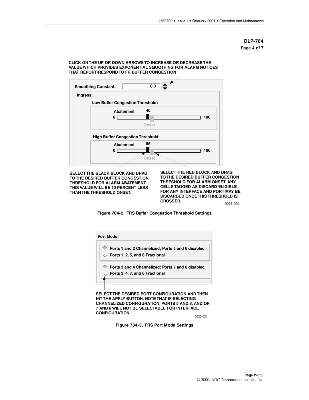
CLICK ON THE UP OR DOWN ARROWS TO INCREASE OR DECREASE THE VALUE WHICH PROVIDES EXPONENTIAL SMOOTHING FOR ALARM NOTICES THAT REPORT/RESPOND TO FR BUFFER CONGESTION
Smoothing Constant: | 0.3 |
Ingress: |
|
Low Buffer Congestion Threshold: | |
Abatement | 40 |
0 | 100 |
| Onset |
High Buffer Congestion Threshold: | |
Abatement | 65 |
0 | 100 |
| Onset |
SELECT THE BLACK BLOCK AND DRAG TO THE DESIRED BUFFER CONGESTION THRESHOLD FOR ALARM ABATEMENT.
THIS VALUE WILL BE 10 PERCENT LESS THAN THE THRESHOLD ONSET.
SELECT THE RED BLOCK AND DRAG TO THE DESIRED BUFFER CONGESTION THRESHOLD FOR ALARM ONSET. ANY CELLS TAGGED AS DISCARD ELIGIBLE FOR ANY INTERFACE AND PORT MAY BE DISCARDED ONCE THIS THRESHOLD IS CROSSED.
Figure 784-2. FRS Buffer Congestion Threshold Settings
Port Mode:
Ports 1 and 2 Channelized; Ports 5 and 6 disabled
Ports 1, 2, 5, and 6 Fractional
Ports 3 and 4 Channelized; Ports 7 and 8 disabled
![]() Ports 3, 4, 7, and 8 Fractional
Ports 3, 4, 7, and 8 Fractional
SELECT THE DESIRED PORT CONFIGURATION AND THEN HIT THE APPLY BUTTON. NOTE THAT IF SELECTING CHANNELIZED CONFIGURATION, PORTS 5 AND 6, AND/OR 7 AND 8 WILL NOT BE SELECTABLE FOR INTERFACE CONFIGURATION.
Figure 784-3. FRS Port Mode Settings
Page
© 2000, ADC Telecommunications, Inc.
