1152700 • Issue 1 • February 2001 • Section 2 Operations and Maintenance
Page 1 of 2
HARDWARE INVENTORY
Summary: This procedure instructs the operator in the steps required to display information for the cards residing in the Cellworx STN system. Inventory status information may be used for documenting card serial numbers and date of manufacture for warranty purposes, or obtaining part numbers for ordering spare cards.
It is assumed that the user has gained access to the system and has launched the Cellworx Vision GUI.
1.From the GUI main display, select the node desired by double clicking on it using the left mouse button.
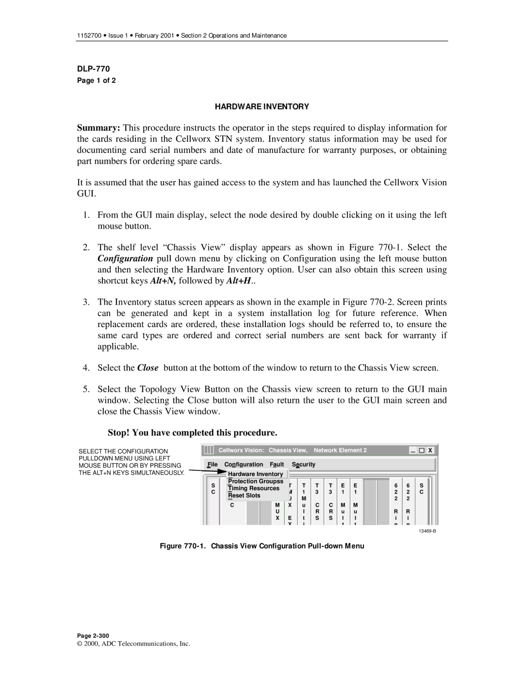
2.The shelf level “Chassis View” display appears as shown in Figure
3.The Inventory status screen appears as shown in the example in Figure
4.Select the Close button at the bottom of the window to return to the Chassis View screen.
5.Select the Topology View Button on the Chassis view screen to return to the GUI main window. Selecting the Close button will also return the user to the GUI main screen and close the Chassis View window.
Stop! You have completed this procedure.
SELECT THE CONFIGURATION PULLDOWN MENU USING LEFT MOUSE BUTTON OR BY PRESSING THE ALT+N KEYS SIMULTANEOUSLY.
| Cellworx Vision: Chassis View, Network Element 2 |
|
| X |
|
|
|
|
|
|
|
File | Configuration | Fault |
| Security |
|
|
|
|
|
|
|
| Hardware Inventory |
|
|
|
|
|
|
|
|
| |
S | Protection Groupss | T | T | T | T E E | 6 | 6 | S | |||
N | T | ||||||||||
C | Timing Resources | M | 1 | 3 | 3 1 1 | 2 | 2 | C | |||
M | 3 | ||||||||||
| Reset Slots | T | U | M |
|
|
|
| 2 | 2 |
|
| I |
|
|
|
|
| |||||
| C | M | X | u | C | C | M | M |
|
|
|
|
| U |
| l | R | R | u | u | R | R |
|
|
| X | E | t | S | S | l | l | i | i |
|
|
|
| X | i |
|
| t | t | n | n |
|
Figure 770-1. Chassis View Configuration Pull-down Menu
Page
© 2000, ADC Telecommunications, Inc.
