1152700 • Issue 1 • February 2001 • Operation and Maintenance
DLP-784
Page 6 of 7
DISPLAYS NE AND CARD TYPE/SLOT INFORMATION.
SELECT THE FIRST CHANNEL AND/OR THE LAST CONTIGUOUS CHANNEL TO CREATE AN INTERFACE.
| Cellworx Vision: Frame Relay Interface |
|
| X | |||
|
|
|
|
|
|
|
|
|
|
|
|
|
|
|
|
Node Name: | Slot Number: | 6 |
|
|
|
| |
|
|
|
|
|
|
|
|
Node ID: | 4 | Card: | FT1 FRS |
|
|
|
|
|
|
|
|
|
|
|
|
Location: | Broadway | Port Number: | 4 |
|
|
|
|
Double click on an interface to display it.
Select a channel number with the left mouse button to start channel selection.
Select a channel number with the right mouse button to end channel selection.
Select a port to switch ports.
Port | Channel | Interface Name: |
| |||||
1 | X | Interface Contact: | default |
|
|
| ||
2 | X |
|
|
| ||||
|
|
|
|
|
|
| ||
3 | X | Interface Location: | default |
|
|
| ||
4 | X | Recording Interface Id: | 0000000000000000 |
|
| |||
|
|
|
| |||||
|
| Operational Status: | Up |
|
|
| ||
Interface selection enabled | Provisioned Endpoints: |
| 0 |
|
|
| ||
Interface creation allowed |
|
|
|
| ||||
1 2 3 4 5 6 7 8 9 | DLCI Length: |
|
| 2 Octets 10 Bits |
|
| ||
|
|
|
|
|
|
| ||
1 | 2 | Used Bandwidth: |
|
|
|
|
| |
Ingress: |
|
| % | Egress: |
| % | ||
|
| 0.00 | 0.00 | |||||
| Current |
|
|
|
|
|
|
|
|
| Effective Bandwidth: |
| 100.00 % |
|
| ||
|
| Interface Type: |
|
| IWF Type: |
|
| |
|
| UNI | NNI |
|
| FRF.5 | FRF.8 |
|
|
| Signaling Parameters |
|
|
|
|
| |
|
| Signaling Protocol: |
|
|
|
|
| |
|
| None | LMI Rev1 |
| Annex D: ANSI T1.617D | Annex A: CCITT Q | ||
SELECT THE APPLY BUTTON AFTER CREATING EACH INTERFACE ON THE PORT.![]()
Apply
Delete
Card View
Refresh
Close
DELETES THE INTERFACE | RETURNS TO THE | REFRESHES | CLOSES THE WINDOW |
SHOWN AS "CURRENT" | CARD VIEW. | SCREEN | AND RETURNS TO THE |
ABOVE. |
| DATA. | CARD VIEW WINDOW. |
|
|
|
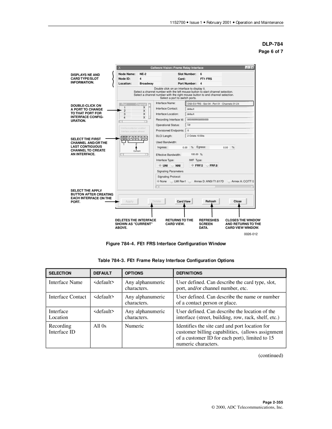
Figure 784-4. FE1 FRS Interface Configuration Window
Table 784-3. FE1 Frame Relay Interface Configuration Options
SELECTION
Interface Name
Interface Contact
Interface
Location
Recording
Interface ID
DEFAULT
<default>
<default>
<default>
All 0s
OPTIONS
Any alphanumeric characters.
Any alphanumeric characters.
Any alphanumeric characters.
Numeric
DEFINITIONS
User defined. Can describe the card type, slot, port, and/or channel number, etc.
User defined. Can describe the name or number of a contact person or place.
User defined. Can describe the location of the interface (street, building, row, rack, shelf, etc.)
Identifies the site card and port location for customer billing capabilities, (allows assignment of a customer ID for each port), limited to 15 numeric characters.
(continued)
Page
© 2000, ADC Telecommunications, Inc.
