1152700 • Issue 1 • February 2001 • Section 2 Operation and Maintenance
DLP-727
Page 2 of 4
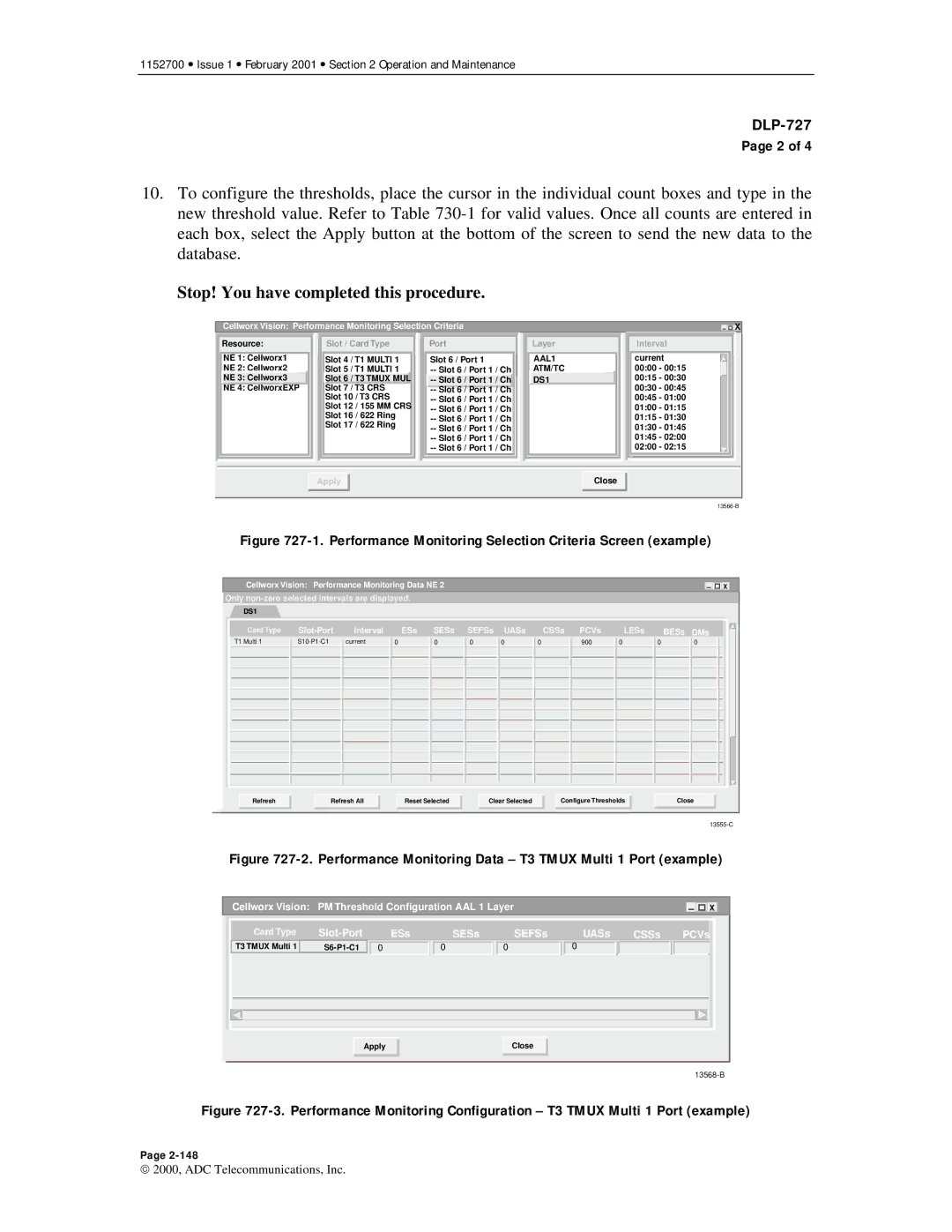
10.To configure the thresholds, place the cursor in the individual count boxes and type in the new threshold value. Refer to Table
Stop! You have completed this procedure.
| Cellworx Vision: Performance Monitoring Selection Criteria |
|
|
|
|
|
| X | |||||||||
| Resource: |
| Slot / Card Type |
| Port |
| Layer |
|
| Interval |
|
| |||||
|
|
|
|
|
|
|
|
|
|
|
|
|
|
|
| ||
| NE 1: Cellworx1 |
| Slot 4 | / T1 | MULTI 1 |
| Slot 6 / Port 1 |
| AAL1 |
| current |
|
| ||||
| NE 2: Cellworx2 |
| Slot 5 | / T1 | MULTI 1 |
|
|
| ATM/TC |
| 00:00 - 00:15 |
|
| ||||
| NE 3: Cellworx3 |
| Slot 6 | / T3 TMUX MUL |
|
|
| DS1 |
|
| 00:15 - 00:30 |
|
| ||||
| NE 4: CellworxEXP |
| Slot 7 | / T3 | CRS |
|
|
|
|
|
| 00:30 - 00:45 |
|
| |||
|
|
| Slot 10 | / T3 CRS |
|
|
|
|
| 00:45 - 01:00 |
|
| |||||
|
|
| Slot 12 | / 155 | MM CRS |
|
|
|
|
| 01:00 - 01:15 |
|
| ||||
|
|
| Slot 16 | / 622 | Ring |
|
|
|
|
| 01:15 - 01:30 |
|
| ||||
|
|
| Slot 17 | / 622 | Ring |
|
|
|
|
| 01:30 - 01:45 |
|
| ||||
|
|
|
|
|
|
|
|
|
|
|
|
|
| 01:45 - 02:00 |
|
| |
|
|
|
|
|
|
|
|
|
|
|
|
|
| 02:00 - 02:15 |
|
| |
|
|
|
|
|
|
|
|
|
|
|
|
|
|
|
|
|
|
|
|
|
|
|
|
|
|
|
|
|
|
|
|
|
|
|
|
|
|
|
|
|
|
|
|
|
|
|
|
|
|
|
|
|
|
Apply |
Close |
Figure 727-1. Performance Monitoring Selection Criteria Screen (example)
Cellworx Vision: Performance Monitoring Data NE 2 |
|
| X |
|
Only
DS1
Card Type
T1 Multi 1
ESs SESs SEFSs UASs
0 | 0 | 0 | 0 |
|
|
|
|
CSSs PCVs
0 | 900 |
|
|
LESs
0
BESs DMs
0 | 0 |
|
|
Refresh | Refresh All |
Reset Selected
Clear Selected
Configure Thresholds
Close
Figure 727-2. Performance Monitoring Data – T3 TMUX Multi 1 Port (example)
Cellworx Vision: | PM Threshold Configuration AAL 1 Layer |
|
| X | |||
Card Type | ESs | SESs | SEFSs | UASs | CSSs | PCVs | |
T3 TMUX Multi 1 | 0 | 0 | 0 | 0 |
|
| |
Apply |
Close |
Figure 727-3. Performance Monitoring Configuration – T3 TMUX Multi 1 Port (example)
Page
2000, ADC Telecommunications, Inc.