1152700 • Issue 1 • February 2001 • Section 2 Operation and Maintenance
Page 3 of 7
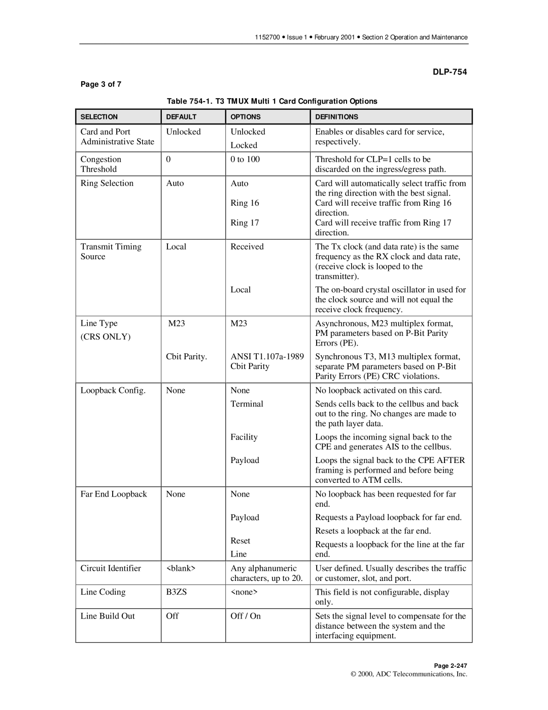
Table 754-1. T3 TMUX Multi 1 Card Configuration Options
SELECTION
Card and Port Administrative State
Congestion
Threshold
Ring Selection
Transmit Timing Source
Line Type (CRS ONLY)
Loopback Config.
Far End Loopback
Circuit Identifier
Line Coding
Line Build Out
DEFAULT
Unlocked
0
Auto
Local
M23
Cbit Parity.
None
None
<blank>
B3ZS
Off
OPTIONS
Unlocked
Locked
0 to 100
Auto
Ring 16
Ring 17
Received
Local
M23
ANSI
None
Terminal
Facility
Payload
None
Payload
Reset
Line
Any alphanumeric characters, up to 20.
<none>
Off / On
DEFINITIONS
Enables or disables card for service, respectively.
Threshold for CLP=1 cells to be discarded on the ingress/egress path.
Card will automatically select traffic from the ring direction with the best signal. Card will receive traffic from Ring 16 direction.
Card will receive traffic from Ring 17 direction.
The Tx clock (and data rate) is the same frequency as the RX clock and data rate, (receive clock is looped to the transmitter).
The
Asynchronous, M23 multiplex format, PM parameters based on
Synchronous T3, M13 multiplex format, separate PM parameters based on
No loopback activated on this card.
Sends cells back to the cellbus and back out to the ring. No changes are made to the path layer data.
Loops the incoming signal back to the CPE and generates AIS to the cellbus.
Loops the signal back to the CPE AFTER framing is performed and before being converted to ATM cells.
No loopback has been requested for far end.
Requests a Payload loopback for far end.
Resets a loopback at the far end.
Requests a loopback for the line at the far end.
User defined. Usually describes the traffic or customer, slot, and port.
This field is not configurable, display only.
Sets the signal level to compensate for the distance between the system and the interfacing equipment.
Page
© 2000, ADC Telecommunications, Inc.
