1152700 • Issue 1 • February 2001 • Section 2 Operation and Maintenance
Page 2 of 7
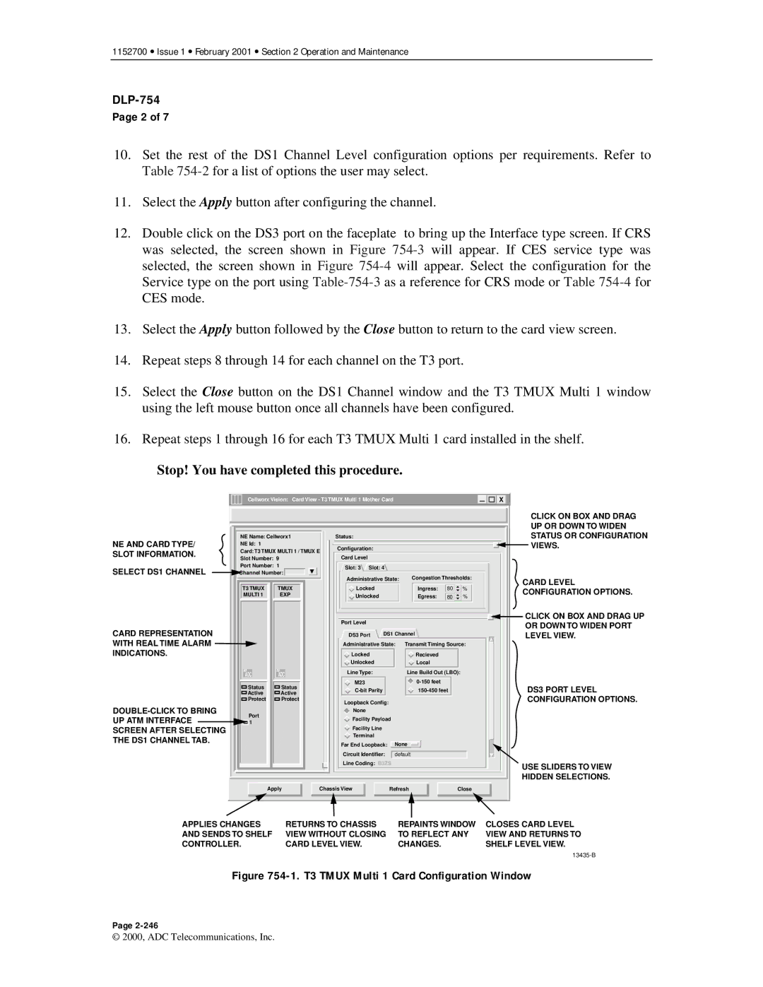
10.Set the rest of the DS1 Channel Level configuration options per requirements. Refer to Table
11.Select the Apply button after configuring the channel.
12.Double click on the DS3 port on the faceplate to bring up the Interface type screen. If CRS was selected, the screen shown in Figure
13.Select the Apply button followed by the Close button to return to the card view screen.
14.Repeat steps 8 through 14 for each channel on the T3 port.
15.Select the Close button on the DS1 Channel window and the T3 TMUX Multi 1 window using the left mouse button once all channels have been configured.
16.Repeat steps 1 through 16 for each T3 TMUX Multi 1 card installed in the shelf.
Stop! You have completed this procedure.
| Cellworx Vision: Card View - T3 TMUX Multi 1 Mother Card |
|
| X |
|
|
|
|
|
|
|
|
|
|
|
| CLICK ON BOX AND DRAG |
|
|
|
|
|
|
| UP OR DOWN TO WIDEN |
NE AND CARD TYPE/ | NE Name: Cellworx1 | Status: |
|
|
| STATUS OR CONFIGURATION | |
NE Id: 1 |
| Configuration: |
|
|
| VIEWS. | |
Card: T3 TMUX MULTI 1 / TMUX E |
|
|
| ||||
SLOT INFORMATION. |
|
|
|
|
| ||
Slot Number: 9 | Card Level |
|
|
|
| ||
SELECT DS1 CHANNEL | Port Number: 1 | Slot: 3 Slot: 4 |
|
|
|
| |
Channel Number: |
|
|
|
| |||
Administrative State: | Congestion Thresholds: |
| |||||
|
|
| CARD LEVEL | ||||
| T3 TMUX | TMUX | Locked | Ingress: | 80 | % | |
| CONFIGURATION OPTIONS. | ||||||
| MULTI 1 | EXP | Unlocked | Egress: | 80 | % | |
|
|
|
| ||||
|
|
|
|
|
|
|
|
|
|
|
|
|
|
|
|
|
|
|
|
|
|
|
|
|
|
|
|
|
|
|
|
|
|
|
|
|
|
|
|
|
|
|
|
|
|
|
|
| CLICK ON BOX AND DRAG UP |
CARD REPRESENTATION |
|
|
|
|
|
|
|
|
|
|
|
|
|
|
|
|
|
|
|
|
| Port Level |
|
|
|
|
|
|
|
|
|
|
|
|
|
|
|
|
|
| OR DOWN TO WIDEN PORT | ||||||||
|
|
|
|
|
|
|
|
|
|
|
|
|
|
|
|
|
|
|
|
| DS3 Port |
|
|
|
|
|
|
|
|
|
|
|
|
|
|
|
|
|
| ||||||||||
|
|
|
|
|
|
|
|
|
|
|
|
|
|
|
|
|
|
|
|
| DS1 Channel |
|
|
|
|
|
|
|
|
| LEVEL VIEW. | ||||||||||||||||||
WITH REAL TIME ALARM |
|
|
|
|
|
|
|
|
|
|
|
|
|
|
|
|
|
|
|
|
|
|
| Administrative State: Transmit Timing Source: |
|
|
|
|
|
|
| ||||||||||||||||||
INDICATIONS. |
|
|
|
|
|
|
|
|
|
|
|
|
|
|
|
|
|
|
|
|
| Locked |
|
|
|
|
| Recieved |
|
|
|
|
|
|
|
|
|
| |||||||||||
|
|
|
|
|
|
|
|
|
|
|
|
|
|
|
|
|
|
|
|
|
|
|
|
|
|
|
| Unlocked |
|
|
|
|
| Local |
|
|
|
|
|
|
|
|
|
| |||||
|
|
|
|
|
|
|
|
|
|
|
|
|
|
|
|
|
|
|
|
|
|
|
|
|
|
|
|
|
|
|
|
|
|
|
|
|
|
|
|
|
|
|
|
|
| ||||
|
|
|
|
|
|
|
| ADC |
|
| ADC |
|
|
|
|
|
|
|
|
|
|
|
| Line Type: |
|
|
|
| Line Build Out (LBO): |
|
|
|
|
|
|
| |||||||||||||
|
|
|
|
|
|
|
|
|
|
|
|
|
|
|
|
|
|
|
|
|
|
|
|
|
|
|
| M23 |
|
|
|
|
|
|
|
|
|
|
|
|
|
|
| ||||||
|
|
|
|
|
|
|
|
|
| Status |
|
|
| Status |
|
|
|
|
|
|
|
|
|
|
|
|
|
|
|
|
|
|
|
|
|
|
|
|
| DS3 PORT LEVEL | |||||||||
|
|
|
|
|
|
|
|
| Active |
|
|
| Active |
|
|
|
|
|
|
|
|
|
|
|
|
|
|
|
|
|
|
|
|
|
|
|
|
| |||||||||||
|
|
|
|
|
|
|
|
|
|
|
|
|
|
|
|
|
|
|
|
|
|
|
|
|
|
|
|
|
|
|
|
|
|
|
|
|
|
|
|
|
|
|
| CONFIGURATION OPTIONS. | |||||
|
|
|
|
|
|
|
|
|
| Protect |
|
|
| Protect |
|
|
|
|
|
|
|
|
|
|
| Loopback Config: |
|
|
|
|
|
|
|
|
|
|
|
|
|
|
|
| |||||||
|
|
|
|
|
|
|
|
|
|
|
|
|
|
|
|
|
|
|
|
|
|
|
|
|
|
|
|
|
|
|
|
|
|
|
|
|
| ||||||||||||
|
|
|
|
|
|
|
|
|
|
|
|
|
|
|
|
|
|
|
|
|
|
|
|
|
|
|
|
|
|
|
|
|
|
|
|
|
|
|
|
|
|
|
|
| |||||
|
|
| Port |
|
|
|
|
|
|
|
|
|
|
|
|
|
|
|
| None |
|
|
|
|
|
|
|
|
|
|
|
|
|
|
|
|
|
|
| ||||||||||
UP ATM INTERFACE |
|
|
|
|
|
|
|
|
|
|
|
|
|
|
|
|
|
|
|
|
|
|
|
|
| Facility Payload |
|
|
|
|
|
|
|
|
|
| |||||||||||||
|
|
|
|
|
|
|
|
| 1 |
|
|
|
|
|
|
|
|
|
|
|
|
|
|
|
|
|
|
|
|
|
|
|
|
|
|
| |||||||||||||
|
|
|
|
|
|
|
|
|
|
|
|
|
|
|
|
|
|
|
|
| Facility Line |
|
|
|
|
|
|
|
|
|
|
|
|
|
|
|
|
|
|
| |||||||||
SCREEN AFTER SELECTING |
|
|
|
|
|
|
|
|
|
|
|
|
|
|
|
|
|
|
|
|
|
|
|
|
|
|
|
|
|
|
|
|
|
|
|
|
|
|
|
| |||||||||
|
|
|
|
|
|
|
|
|
|
|
|
|
|
|
|
|
|
|
|
| Terminal |
|
|
|
|
|
|
|
|
|
|
|
|
|
|
|
|
|
|
| |||||||||
THE DS1 CHANNEL TAB. |
|
|
|
|
|
|
|
|
|
|
|
|
|
|
|
|
|
|
|
|
|
|
|
|
|
|
|
|
|
|
|
|
|
|
|
|
|
|
|
|
|
|
| ||||||
|
|
|
|
|
|
|
|
|
|
|
|
|
|
|
|
|
|
|
|
| Far End Loopback: |
| None |
|
|
|
|
|
|
|
|
|
|
|
|
| |||||||||||||
|
|
|
|
|
|
|
|
|
|
|
|
|
|
|
|
|
|
|
|
|
|
|
|
|
|
|
| Circuit Identifier: |
|
|
|
|
|
|
|
|
|
|
|
|
|
|
|
|
| ||||
|
|
|
|
|
|
|
|
|
|
|
|
|
|
|
|
|
|
|
|
|
|
|
|
|
|
|
|
| default |
|
|
|
|
|
|
|
|
|
| ||||||||||
|
|
|
|
|
|
|
|
|
|
|
|
|
|
|
|
|
|
|
|
|
|
|
|
|
|
|
| Line Coding: B3ZS |
|
|
|
|
|
|
|
| USE SLIDERS TO VIEW | ||||||||||||
|
|
|
|
|
|
|
|
|
|
|
|
|
|
|
|
|
|
|
|
|
|
|
|
|
|
|
|
|
|
|
|
|
|
|
|
|
|
|
|
|
|
|
|
|
|
|
| ||
|
|
|
|
|
|
|
|
|
|
|
|
|
|
|
|
|
|
|
|
|
|
|
|
|
|
|
|
|
|
|
|
|
|
|
|
|
|
|
|
|
|
|
|
|
|
|
| HIDDEN SELECTIONS. | |
|
|
|
|
|
|
|
|
|
|
|
|
|
|
|
|
|
|
|
|
|
|
|
|
|
|
|
|
|
|
|
|
|
|
|
|
|
|
|
|
|
|
|
|
|
|
|
| ||
|
|
|
|
|
|
|
|
|
| Apply |
|
|
| Chassis View |
|
|
|
| Refresh |
|
| Close |
|
|
|
|
|
|
| ||||||||||||||||||||
|
|
|
|
|
|
|
|
|
|
|
|
|
|
|
|
|
|
|
|
|
|
|
|
|
|
|
|
|
|
|
|
|
|
|
|
|
|
|
|
|
|
|
|
|
|
|
|
|
|
|
|
|
|
|
|
|
|
|
|
|
|
|
|
|
|
|
|
|
| ||||||||||||||||||||||||||||||
APPLIES CHANGES |
|
|
|
| RETURNS TO CHASSIS |
|
|
| REPAINTS WINDOW | CLOSES CARD LEVEL | |||||||||||||||||||||||||||||||||||||||
AND SENDS TO SHELF |
|
|
|
| VIEW WITHOUT CLOSING |
| TO REFLECT ANY | VIEW AND RETURNS TO | |||||||||||||||||||||||||||||||||||||||||
CONTROLLER. |
|
|
|
|
|
|
|
|
| CARD LEVEL VIEW. |
|
|
| CHANGES. |
|
|
| SHELF LEVEL VIEW. | |||||||||||||||||||||||||||||||
|
|
|
|
|
|
|
|
|
|
|
|
|
|
|
|
|
|
|
|
|
|
|
|
|
|
|
|
|
|
|
|
|
|
|
|
|
|
|
|
|
|
|
|
|
|
|
|
| |
Figure 754-1. T3 TMUX Multi 1 Card Configuration Window
Page
© 2000, ADC Telecommunications, Inc.