Brocade Network Advisor
Title Publication number Summary of changes Date
Brocade Communications Systems, Incorporated
Title Publication number Summary of changes Date
53-1003056-01
Contents
Chapter Discovery
Installing a patch Uninstalling a patch
Vii
Management groups overview
Configurable preferences
Displaying Network Object view
111
Users overview
Viewing configured users
181
182
Setting the dashboard display
Accessing a dashboard
Dashboard overview
Dashboard toolbar
53-1003056-01
IP main toolbar
IP tab overview
Product List toolbar
Host Product List toolbar
Call Home overview
Viewing Call Home configurations
System requirements
344
Starting third-party tools from the application
About third-party tools
Launching a Telnet session
Launching an Telnet session from the IP tab
Wireless devices
Wireless management overview
Server Management Console overview
Launching the SMC on Windows
Logical chassis cluster mode discovery
VCS mode types
VCS
Ethernet Fabrics view management
Brocade adapters
Host management
Host Bus Adapters
Converged Network Adapters
481
This chapter
Telemetry overview
Adding policies from saved configurations
Policy-based routing
Viewing existing PBR policies
IronWare Layer 2 ACL configuration
Layer 2 access control list management
Fabric OS Layer 2 ACL configuration
Creating a Layer 2 ACL from a saved configuration
Zoning overview
Scheduling a security configuration deployment
Online zoning
Offline zoning
671
Chapter Port Fencing
723
Chapter IP Element Manager
765
743
777
CLI configuration overview
778
807
Remote Switched Port Analyzer
Default Vlan
Configuration requirements for Vlan Manager
Adding or modifying dual mode ports
843
Mpls pre-configuration
VIP Servers overview
VIP Server functions
917
Chapter SSL Certificates for ServerIron Products
Xxx 53-1003056-01
Chapter Power Center
Chapter Policy Monitor
Fault Management
Chapter Technical Support
This chapter 1213 Configuring packet captures
Reports
Link incident events
Dashboard main menus 1261 IP main menus IP shortcut menus
Product status events
1277
This appendix
Database tables and fields
1371
Xxxviii 53-1003056-01
Xxxix
Wirelessinterface Wiredinterface Ceeportinfo
About This Document
This chapter
How this document is organized
Xliv 53-1003056-01
Fabric OS hardware and software support
Supported hardware and software
IronWare hardware and software support
Xlvii
Xlviii 53-1003056-01
Xlix
Network OS hardware and software support
What’s new in this document
Text formatting
Document conventions
Key terms
Bold text
Brocade resources
Additional information
Other industry resources
These references are made for informational purposes only
Document feedback
Getting technical help
User interface components
Getting Started
Management server and client
Management server and client
Logging into a server
Clearing previous versions of the remote client
Launching a remote client
Launching the Configuration Wizard
53-1003056-01
53-1003056-01
Viewing active sessions
Select Server Active Sessions
Active Sessions dialog box displays Figure
Viewing server properties
Disconnecting users
To disconnect a user, complete the following steps
Select Server Server Properties
Management server and client Server Properties
Viewing port status
Click Close to close the Server Properties dialog box
Field/Component Description
Server and client ports
Tftp UDP
TCP
4431,2 Https server
Json
Accessibility features for the Management application
Accessibility features for the Management application
Keyboard shortcuts
Menu Item or Function Keyboard Shortcut
Look and feel customization
Setting the look and feel
Select Server Options
Options dialog box displays
Connecting to the database using pgAdmin
PostgreSQL database
Changing the font size
Selecting File Add Server
PostgreSQL database
Click the System DSN tab Click Add
Odbc Data Source Administrator dialog box displays
Linux version RedHat Package Manager file
Suse
On the Setup psqlODBC screen click Next
Installing the Odbc driver on Linux systems
Adding the Datasourse on Linux systems
Save and close the odbcinst.ini file
Executing SQL queries from the CLI
Testing the connection on Linux systems
On the Select database screen, complete the following steps
Select the Connect to an existing database option
Changing the database user password
Supported open source software products
Open Source Software License Type
HP Software Development KIT License Agreement
Lgpl
BSD
Ireasoning
Open Source Software License Type
Supported open source software products
Installing a patch
Patches
Execute the patch file for your operating system
Uninstalling a patch
53-1003056-01
Uninstalling a patch
Discovery
IP discovery overview
IP discovery overview
53-1003056-01
Discovery of IPv6 addresses
Configuration requirements
MIB support
Ietf standard MIB name Required MIB object Data collected
MIB-II
IF-MIB
BRIDGE-MIB
Ietf standard MIB name Required MIB object Data collected
VDX/VCS discovery
ENTITY-MIB
IP-MIB
VCS in-band management interface discovery
Network OS discovery IP address format
Mapping VCS in-band management
1000000533516242
VCS fabric discovery
Standalone discovery
VCS fabric rediscovery
Select File Save
Seed switch failover
VCS fabric split and merge
Network OS 2.0 device limitations
Logical chassis cluster mode discovery
Discover Setup IP dialog box before removal of node
How the Management application handles a cluster mode change
Discover Setup IP dialog box displays
Configuring IP profile discovery
HyperEdge stack discovery
HyperEdge stack discovery
Click the Global Settings tab
Configuring IP profile discovery
Configuring IP simple discovery
Configuring IP simple discovery
IP Snmp credentials
Adding SNMPv1 and SNMPv2c credentials
Click the Snmp tab
IP Snmp credentials
Adding SNMPv3 credentials
HMACMD5 Hmacsha
CBC-DES
Editing SNMPv1 and SNMPv2c credentials
Editing SNMPv3 credentials
Deleting Snmp credentials from the list
Reordering Snmp credentials in the list
Adding user credentials
Default IP user credentials
Default IP user credentials
53-1003056-01
Editing enable prompt user credentials
Editing login prompt user credentials
To edit an enable super user, complete the following steps
Editing enable super user credentials
Deleting user credentials from the list
Reordering user credentials in the list
Including product types
IP Object identifier filters
IP Object identifier filters
Click the OID Filter tab
Product sysObjectID Vendor
Excluding product types
Defining global setting preferences
Defining global setting preferences
Deleting product types from the list
Click the Preferences tab
53-1003056-01
Reduce the managed count by completing the following steps
Configuring event-based collection
53-1003056-01
Configuring a discovery profile
IP discovery profiles
IP discovery profiles
Duplicating a discovery profile
Configuring address ranges
Select Cidr Subnet from the Entry Type list
Adding Cidr subnet addresses
Adding IP addresses
Adding subnet addresses
Excluding subnet addresses
Excluding Cidr subnet addresses
Excluding IP addresses
Editing address ranges
Editing Cidr subnet addresses
Editing subnet addresses
Editing IP addresses
Scheduling discovery
Configuring an hourly discovery schedule
Configuring a one-time discovery schedule
Configuring a weekly discovery schedule
Configuring a daily discovery schedule
Configuring a yearly discovery schedule
Configuring a monthly discovery schedule
Suspending a discovery schedule
Editing a discovery schedule
To edit a discovery schedule, complete the following steps
Editing an hourly discovery schedule
Editing a one-time discovery schedule
Editing a daily discovery schedule
Editing a weekly discovery schedule
Configuring advanced discovery profile preferences
Editing a monthly discovery schedule
Editing a yearly discovery schedule
IP discovery profiles
Deleting a discovery profile
Creating a discovery address file
Starting discovery manually
Stopping discovery
Starting discovery automatically
Viewing discovery status
To view discovery status, complete the following steps
Mailing discovery reports
Viewing discovery reports
Exporting discovery reports
Viewing the discovery log
Click Discovery Log
Individual IP device discovery
Adding an IP device to discovery
Individual IP device discovery
HMACMD5
Click the SNMPv1/v2c Read/Write tab
Click the SNMPv3 Read Only tab
Editing IP device discovery
Click the SNMPv1/v2c Read Only tab
Click the Read/Write Credentials tab
Click the SNMPv3 Read/Write tab
Click the SNMPv1/v2c Read/Write. tab
Click the SNMPv1/v2c Read Only tab
Click the Port Config Credentials tab
53-1003056-01
Deleting IP devices from discovery
Host discovery
Discovering Hosts by Network address or host name
Select Discover Host Adapters
Host discovery
Click Close on the Discover Host Adapters dialog box
Importing Hosts from a CSV file
Host discovery
Importing Hosts from a Fabric
Importing Hosts from a VM manager
Host discovery
To edit Host credentials, complete the following steps
Editing Host adapter credentials
Rediscovering a previously discovered fabric
Removing a host from active discovery
Deleting a host adapter from discovery
Click Discover
Troubleshooting host discovery
Viewing the host discovery state
IconDescription
VM Manager discovery requirements
VM Manager discovery
Discovering a VM manager
Select Discover VM Managers
VM Manager discovery
Clear to disable vSphere client plug-in registration
Editing a VM manager
Click Close on the Discover VM Managers dialog box
To edit VM manager discovery, complete the following steps
Including a host in VM manager discovery
Excluding a host from VM manager discovery
Removing a VM manager from active discovery
Rediscovering a previously discovered VM manager
Viewing the VM manager discovery state
Deleting a VM manager from discovery
Troubleshooting VM manager discovery
IP Rediscovery
Rediscovering IP devices
Click Rediscover
Rediscovering IP devices from the Product List
Rediscovering a group
Enabling password validation on rediscovery
Management Groups
Management groups overview
Displaying Network Object view
Product group overview
Creating a static product group
Static product groups
Product group overview
Editing a static product group
Duplicating a static product group
Creating a dynamic product group
Dynamic product groups
Userdefinedproperty1 up to
Select Value or Regular Expression from the Type list
Duplicating a dynamic product group
Editing a dynamic product group
Viewing product group properties
Viewing test results
Product Group Properties dialog box displays
Properties tab
Click OK to close the dialog box
Products tab
Performance list
Deleting a product group
Port Groups
Creating a port group
Port Groups
Editing a port group
Duplicating a port group
Ports tab
Viewing port group properties
Deleting a port group
Configurable preferences
Application Configuration
Server Data backup
Management server backup
What is backed up?
Configuring backup
Select Server Backup in the Category list
130 53-1003056-01
Enabling backup
Viewing the backup status
Disabling backup
Changing the backup interval
Clear the Enable Backup check box Click Apply or OK
Starting immediate backup
Reviewing backup events
Select Server Backup in the Category list Click Backup Now
Restoring data
Server Data restore
Restoring data to a new server
SAN data collection
136 53-1003056-01
Product communication protocols
Icmp
Snmp
FTP
Netconf
Configuring event storage
Event storage settings
Event storage settings Product communication protocols
To configure event storage, complete the following steps
Configuring flyovers
Flyover settings
Storing historical events purged from repository
Select Event Storage in the Category list
Options dialog box Flyovers pane, Connection tab
Properties table
Name settings
Turning flyovers on or off
Viewing flyovers
Select Configure Names
Fixing duplicate names
Click Fix Duplicates
Name settings Select one of the following options
Configure Names dialog box displays Figure
Viewing names
Adding a name to an existing device
Adding a name to a new device
Applying a name to a detached WWN
Click Apply Names
Editing names
Removing a name from a device
Exporting names
Click Export
Searching for a device by name
Importing Names
To import names, complete the following steps
Click Import
Searching for a device by WWN
Miscellaneous security settings
Configuring the server name
Configuring login security
Select Security Misc in the Category list
Configuring the login banner display
Syslog Registration settings
Disabling the login banner
Registering a server as a Syslog recipient automatically
Snmp Trap Registration settings
Configuring the Syslog listing port number
Registering a server as a Snmp trap recipient automatically
Configuring the Snmp trap listing port number
Snmp Trap forwarding credential settings
Configuring Snmp v1 and v2c credentials
Snmp Trap forwarding credential settings
Configuring Snmp v3 credentials
Software Configuration
Configuring the server IP address
Client/Server IP
156 53-1003056-01
Configuring an explicit server IP address
Click OK on the Login Banner
Configuring the application to use dual network cards
Software Configuration
You can configure the following preferences for IP products
IP preferences
Configuring change manager preferences
Configuring custom report preferences
Configuring deployment preferences
Configuring deployment report preferences
Configuring image repository preferences
Configuring IP device manager preferences
Configuring Mpls management preferences
Configuring Mpls polling service preferences
Configuring polling service preferences
Configuring name service preferences
Configuring sFlow accounting preferences
Configuring sFlow data collector preferences
Configuring SSL certificates preferences
Configuring sFlow monitoring preferences
Configuring Snmp preferences
Configuring syslog file reader preferences
Configuring Tftp preferences
Configuring memory allocation settings
Memory allocation settings
Server Heap Size
Configuring asset polling
Product communication settings
Configuring SAN communication
Viewing the network size status
Configuring the preferred IP format
Select the Connect using Http option
Select the Connect using Https Http over SSL only option
Configuring IP communication
Http
FTP/SCP/SFTP server settings
Configuring an internal FTP server
Accessing the FTP server folder
Configuring an internal SCP or Sftp server
Select the Use External FTP Server and/or SCP Server option
Configuring an external FTP, SCP, or Sftp server
Select SCP from the Preferred Protocol Secured list
Testing the FTP, SCP, and Sftp server
Select Sftp from the Preferred Protocol Secured list
Select FTP/SCP/SFTP in the Category list
Server port settings
Configuring the server port
To configure server settings, complete the following steps
Configuring support mode settings
Support mode settings
Select Support Mode in the Category list
Options dialog box displays Figure
Configuring the server log file purge limit
Fips Support
Users overview
User Account Management
To view configured users, complete the following steps
Viewing configured users
Select Server Users
Users dialog box displays Click the Users tab, if necessary
183
184 53-1003056-01
Creating a new user account
User accounts
User accounts
To create a new user account, complete the following steps
186 53-1003056-01
Copying a user account
Editing a user account
Copying and pasting user preferences
Disabling a user account
Deleting a user account
Enabling a user account
Unlocking a user account
To re-activate a user account, complete the following steps
Creating a new role
Roles
Roles
To create a new role, complete the following steps
Copying a role
Editing a role
Deleting a role
Adding privileges to a role
To delete a role, complete the following steps
Areas of responsibility
Removing privileges from a role
Areas of responsibility
Creating an AOR
Copying an AOR
Editing an AOR
Assigning products to an AOR
Deleting an AOR
Configuring a password policy
Password policies
Removing products from an AOR
Users dialog box displays Click the Policy tab
199
Viewing password policy violators
Click the Authentication Server Groups tab
Authentication Server Groups on the Management server
Assigning roles and AORs to an AD group
Click View Policy Violators
Removing roles and AORs from an AD group
Loading an AD group
To load an AD group, complete the following steps
Creating an AD user account
Deleting an AD group
Open the Active Directory Users and Computers console
Close the Active Directory Users and Computers dialog box
Configuring roles and AORs on the external Ldap server
Assigning an AD user to an AD group
Defining user accounts on the external Ldap server
User profiles
Click OK Close the Management console
Select Start Run Type adsiedit.msc and press Enter
Viewing your user profile
User profiles Configure CLI credentials
Select Server User Profile
Click OK on the User Profile dialog box
Editing your user profile
Changing your password
User profiles
To edit your user profile, complete the following steps
To view your password policy, complete the following steps
Viewing your password policy
Configuring e-mail notification
Resetting optional messages
Configuring CLI credentials
Click Optional Messages Reset
Configuring the CLI credential policy
Dashboard overview
Dashboard Management
212 53-1003056-01
Toolbar
Dashboard toolbar
Dashboards expand navigation bar
Dashboard messages
General dashboard functions
Accessing a dashboard
Creating a user-defined dashboard
Filtering the dashboards list
Setting the dashboard display
Deleting a user-defined dashboard
Customizing the dashboard widgets and monitors
218 53-1003056-01
Exporting the dashboard display
Printing the dashboard display
Attaching and detaching the Dashboard tab
Setting the network scope
Creating a customized network scope
Setting the data display time frame
Editing a user-defined network scope
Deleting a user-defined network scope
Default dashboards
Product Status and Traffic dashboard
IP Port Health
Access Point Status widget
Status widgets
Status widgets
Color Type
Customizing the Access Point Status widget
ColorSeverity
Events widget
Customizing the Events widget
Accessing additional data from the Events widget
Customizing the Host Adapter Inventory widget
Host Adapter Inventory widget
IP Inventory widget
Customizing the IP Inventory widget
Accessing additional data from the IP Inventory widget
IP Status widget
IP Status widget displays the device status as a pie chart
Viewing additional IP product data
Accessing additional data from the IP Status widget
Fabric Watch widgets
Status widget
Fabric Watch widgets
Out of Range Violations widget
Customizing the Out of Range Violations widget
Port Health Violations widget
Customizing the Port Health Violations widget
Accessing additional data from the widget
Performance monitors
Monitor title Description Data collectors
Performance monitors Preconfigure performance monitors
Displaying monitors on the Performance Dashboard
Click the Customize Dashboard icon
Top Port Alignment Errors monitor
Accessing additional data from top or bottom port monitors
Performance monitors Click OK
Performance monitors
Top Port C3 Discards monitor
Top Port C3 Discards RX to monitor
Top Port CRC Errors monitor
243
Top Port Discards monitor
Accessing additional data from the Top Port Discards monitor
Top Port Encode Error Out monitor
Top Port Errors monitor
Top Port Errors monitor
Accessing additional data from the Top Port Errors monitor
Top Port Overflow Errors monitor
Top Port Receive EOF monitor
Top Port Runtime Errors monitor
Top Port Sync Losses monitor
Top Port Too Long Errors monitor
Top Port Traffic monitor
Accessing additional data from the Top Port Traffic monitor
Top Port Underflow Errors monitor
Top Port Utilization Percentage monitor
255
Bottom Port Utilization Percentage monitor
Top Product CPU Utilization monitor
Top Product Memory Utilization monitor
Top Product Response Time monitor
Top Product Temperature monitor
261
Top Products with Unused Ports monitor
Editing a preconfigured performance monitor
User-defined performance monitors
Monitor types
Measures
Top or bottom product performance monitors
Top or bottom port performance monitors
Distribution performance monitors
Port measures types
User-defined performance monitors
Time series performance monitors
Accessing additional data from the Distribution monitors
Accessing additional data from the sFlow monitors
Configuring a user-defined product performance monitor
Top sFlows performance monitors
Add Performance Dashboard Monitor dialog box displays
271
Click OK on the Add Performance Dashboard Monitor dialog box
Adding targets to a user-defined performance monitor
Performance Dashboard Monitor Targets dialog box displays
Configuring a user-defined port performance monitor
274 53-1003056-01
MAC Vlan
Configuring a user-defined sFlow performance monitor
Viewing product distribution data details
Viewing port distribution data details
Configuring a monitor from a performance graph
Utilization Legend
View Management
IP tab overview
Main toolbar
IP main toolbar
Product List toolbar
Topology Map toolbar
Host Product List toolbar
IP Product List
Host topology map toolbar
Product List functions
Topology Map
286 53-1003056-01
Master Log
IP tab overview Topology keyboard shortcuts
Keyboard Shortcut Description
Anchoring or floating the Minimap
Minimap
Resizing the Minimap
Status bar
IP product icons
Icon legend
Icon legend
Host product icons
Vlan
CNA
IP port icons
IP group icons
IP product status icons
Event icons
Zooming in and out of the Connectivity Map
Customizing the main window
Zooming
Customizing the main window
Customizing application tables
Exporting the topology
Zooming out
Displaying columns
Changing the order of columns
Sorting table information
Resizing the columns
Copying table information
Exporting table information
Adding a property label
Product List customization
Searching for information in a table
Expanding and collapsing tables
Deleting a property label
Editing a property label
Searching for a device
Search
Restricting a search by node
Searching for an exact match
Address Finder
Clearing search results
Address Finder
Finding IP addresses
Select Tools Address Finder
Address Finder dialog box displays
303
Finding MAC addresses
305
IP topology view manager
Network Object view functions
Network Objects view
Filtering devices in the Network Objects Product List
Clearing the Network Objects Product List filter
Network Objects view
IP Topology view
L2 Topology view
IP Topology view
Vlan Topology view
Ethernet Fabrics view
STP/RSTP topology
Ethernet Fabrics view
ElementDescription
Viewing STP/RSTP topology
Exporting an STP/RSTP Report
Generating an STP/RSTP Report
Vlan Topology view STP/RSTP Topology map elements
Element Description
Host Topology view
Mailing an STP/RSTP Report
Host Topology view Click Save
314 53-1003056-01
IP topology map components
Topology map elements
IP topology map components
Icon Description Products
Logical
Connections
Topology map layout
Viewing flyovers on the topology map
Orthogonal
Organic
Hierarchical
Orthogonal Merge Lines
Selecting a topology map layout
Circular
Free Form
Creating a customized layout
Creating customized topology links
Customizing the Topology Map
Adding a background image to a map
Click OK on the Topology Background Map dialog box
Deleting a background image from the library
Select Portrait or Landscape from the Orientation area
Printing a map
Enabling port actions
Port actions
Disabling port actions
Displaying port properties for an attached device
Port actions
Accessing performance monitoring
330 53-1003056-01
MRP Topology overview
MRP Topology
Viewing a MRP Topology map
Master
Viewing a MRP ring
Viewing a MRP ring MRP Topology map elements
Error
Selecting a topology map layout
Configuring the application to show a dashed line
336 53-1003056-01
337
Creating a customized layout
Customizing the MRP Topology map
Click the Starting Point row
Enter the ring ID, for example, Ring
Refreshing MRP Topology data
Viewing MRP properties
Click Close on the MRP Topology Options dialog box
341
Viewing MRP properties
Call Home
Call Home
System requirements
Viewing Call Home configurations
346
347
Hiding a Call Home center
Showing a Call Home center
Showing a Call Home center
To show a Call Home center, complete the following steps
Editing a Call Home center
Editing the IBM Call Home center
Click Edit Centers beneath the Call Home Centers list
Editing an e-mail Call Home center
Backup Connection field
Primary Connection field
Click Edit Centers beneath the Call Home Centers table
Enter a password in the Smtp Server Settings Password field
Enter a user name in the Smtp Server Settings Username field
Call Home alert e-mail messages
Fcip
Editing the EMC Call Home center
Editing the HP LAN Call Home center
To enable a Call Home center, complete the following steps
Enabling a Call Home center
Enabling supportSave
Testing the Call Home center connection
Testing the Call Home center connection
Disabling a Call Home center
Select Monitor Event Notification Call Home
Viewing Call Home status
Viewing Call Home status
Removing a device from a Call Home center
Assigning a device to the Call Home center
Removing all devices and filters from a Call Home center
Assigning a device to the Call Home center
Defining an event filter
To define an event filter, complete the following steps
Click OK on the Call Home Event Filter dialog box
Assigning an event filter to a Call Home center
Assigning an event filter to a device
Assigning an event filter to a Call Home center
Overwriting an assigned event filter
Removing all event filter from a Call Home center
Overwriting an assigned event filter
Removing an event filter from a device
Searching for an assigned event filter
Removing an event filter from a device
Searching for an assigned event filter
Third-party tools
About third-party tools
Starting third-party tools from the application
Launching an Element Manager
Launching a Telnet session
Launching an Telnet session from the IP tab
Select Tools Product Menu ToolName
Select Tools Setup
Select Configure Element Manager HCM. HCM Agent displays
Launching HCM Agent
Adding a tool
Entering the server IP address of a tool
Adding an option to the Tools menu
Removing an option from the Tools menu
Changing an option on the Tools menu
Adding an option to a device’s shortcut menu
Changing an option on a device’s shortcut menu
Removing an option from a device’s shortcut menu
374 53-1003056-01
Server Management Console
Server Management Console overview
Launching the SMC on Windows
Monitoring and managing Management application services
Services tab
Services tab
Launching the SMC on Linux
Stopping the Cimom services
Stopping all services
Refreshing the server status
Click Stop Cimom
Restarting all services
Starting all services
Changing the database password
Click Change Database Password
Viewing server port numbers
Ports tab
Configuring Radius server authentication
AAA Settings tab
AAA Settings tab
Select Radius Server from the Primary Authentication list
Local Database
Configuring a Radius server
Configuring Ldap server authentication
Select Ldap Server from the Primary Authentication list
Configuring an Ldap server
For Primary Authentication, select TACACS+ Server
Configuring TACACS+ server authentication
Configuring a TACACS+ server
Configuring Common Access Card authentication
Select CAC from the Primary Authentication list
For Primary Authentication, select Switch
Configuring switch authentication
For Primary Authentication, select Windows Domain
Configuring Windows authentication
Displaying the client authentication audit trail
Configuring local database authentication
For Primary Authentication, select Local Database
Authentication Audit Trail log displays
Technical Support Information tab
Restore tab
Restoring the database
Capturing technical support information
HCM Upgrade tab
To upgrade HCM, complete the following steps
Upgrading HCM on the Management server
SMI Agent Configuration Tool Select the HCM Upgrade tab
SMI Agent Configuration Tool
Launching the Smia configuration tool on Windows
SMI Agent Configuration Tool
Management Console dialog box
Smia Configuration Tool dialog box
Launching the Smia configuration tool on Unix
Launching a remote Smia configuration tool
Service Location Protocol SLP support
Smia Configuration Tool dialog box displays
Slptool commands
SLP file locations on Unix systems
SLP on Unix systems
SLP file locations on Windows systems
SLP on Windows systems
Home tab
Authentication tab
Authentication tab
Click the Authentication tab
Configuring Cimom server authentication
Cimom tab
Configuring the SMI Agent port number
Configuring the Cimom Bind Network Address
Configuring the Cimom log
Certificate Management tab
To import a certificate, complete the following steps
Click the Certificate Management tab
Exporting a certificate
Viewing a certificate
Deleting a certificate
Summary tab
SMI Agent Configuration Tool Click the Summary tab
Log Level
Managed Ports
Licensed Ports
412 53-1003056-01
Wireless management overview
Wireless Management
Wireless devices
Wireless device discovery
Device Name Firmware required
Wireless devices on the dashboard
Wireless devices on the dashboard
View management
Wireless device properties
Element Manager
View management
Launching the Element Manager
Browser and system requirements
Launching a Telnet session
Configuration repository and backup management
Save and close the file
CLI configuration management
Vlan management
Cluster mode
Fault management
Performance management
Policy Monitors
AP Products report
Firmware version
Status
Location
Contact
424 53-1003056-01
VCS
VCS Management
Fabric cluster mode
VCS mode types
Logical chassis cluster operations
Logical chassis cluster mode discovery
Ethernet Fabrics view management
This section contains these topics
428 53-1003056-01
429
Serial firmware update and activation for Network OS devices
Network OS
Support for Network OS VDX 2740 embedded switch
Port profiles
VCS product groups
Static product group
Dynamic product group
Ampp characteristics
Life of a port profile
Port profile Vlan profile QoS profile
Ampp event Applicable behavior and failures
Ampp events and behavior
Assigning MAC addresses to a port profile
Port profile configuration using the management application
Related topics
Managing offline MAC addresses
Click Add Assign MACs dialog box displays
Click Add Offline MACs
Comparing port profiles
Profile Comparison Summary dialog box
Vlan Settings
Profile Comparison Summary list
Profile Properties
ACL Settings
QoS Settings
FCoE Settings
Deploying port profiles
FRU monitoring
System Monitor support on Network OS VDX platforms
System thresholds
Alert notifications
Resource monitoring
Security monitoring
SFP parameter monitoring
Port statistics monitoring
SFP parameter Description Suggested SFP impact
Interface error types
Ethernet fabric traceroute
Select Monitor Diagnostics Traceroute
Tracing Ethernet fabric routes
To diagnose traceroute, you can do either of the following
Source address format Condition
TCP UDP
Request Source port number Destination port number
Ethernet fabric traceroute Trace Route example
Browse to the directory where you want to save the data
Exporting diagnostic data
450 53-1003056-01
Host management
Host Management
Host Bus Adapters
Brocade adapters
Following sections describe the three Brocade adapter types
Model number Description
Fabric Adapters
Converged Network Adapters
HCM software
AnyIOTM technology
HCM software
HCM features
VM Manager
Host adapter discovery
Adding a VM Manager
Click Add on the Discover VM Managers dialog box
HCM and Management application support on ESXi systems
Deleting a VM Manager
ESXi CIM listener ports
Add Host Adapters dialog box
Adding host adapter credentials for ESXi
Adapter software
Select Host Adapter Software from the Configure menu
Adapter software
Select CIM server ESXi only as the Contact option
Importing a driver into the repository
Driver repository
Deleting a driver file from the repository
Boot image repository
Boot Image Management dialog box
Importing a boot image into the repository
Click Import on the Boot Image Repository dialog box
Downloading a boot image to a selected host
Configuring host adapter ports
Bulk port configuration
Deleting a boot image from the repository
Backing up boot image files
Bulk port configuration
Adding a port configuration
Click Add on the Configure Host Adapter Ports dialog box
Add Port Configuration dialog box, shown in , displays
466 53-1003056-01
Adapter Port Configuration Status dialog box displays
Editing a port configuration
Configuring FAWWNs on switch ports
Duplicating a port configuration
Deleting a port configuration
Disabling the Fawwn feature on a switch or AG ports
Enabling the Fawwn feature on a switch or AG ports
Select Configure Fabric Assigned WWN. or
Click Start to save the changes to the switch
Auto-assigning a Fawwn to a switch or AG port
Manually assigning a Fawwn to a switch or AG port
Modifying a Fawwn on a switch or AG port
FAWWNs on attached AG ports
Deleting a Fawwn from a switch or AG port
Adding AG port FAWWNs
Moving an AG port Fawwn across switches
Deleting AG port FAWWNs
Click the Attached AG Ports tab
Host adapter administrator privileges
Role-based access control
Role-based access control
Host adapter management privileges
FC port measures HBA port measures CNA port measures
Host performance management
Host security authentication Counters
Host security authentication
Host security authentication
Host fault management
SupportSave on adapters
Adapter events
Host fault management
Filtering event notifications
Syslog forwarding
Backup support
Configuring backup to a hard drive
Select the Include FTP Root directory check box
Select the Enable Backup check box Click Apply or OK
FCoE overview
Fibre Channel over Ethernet
Enhanced Ethernet features
Enhanced Ethernet features
Dcbx protocol
Enhanced Transmission Selection
Ethernet jumbo frames
FCoE protocols supported
Ethernet link layer protocols supported
FCoE protocols
Saving running configurations
Copying switch configurations to selected switches
FCoE licensing
Saving running configurations
Device type Configuration possibilities
DCB configuration management
Switch policies
Switch policies
DCB map and Traffic Class map
Lldp profiles
DCB configuration
Minimum DCB configuration for FCoE traffic
DCB configuration
Creating a DCB map to carry the LAN and SAN traffic
Select Configure DCB
To configure LLDP, complete the following steps
Configuring Lldp
To configure the DCB interface, complete the following steps
Select Assign the Global Configuration
Select Configure Element Manager Admin
Creating the FCoE Vlan to carry FCoE traffic
Save the running-config file to the startup-config file
Adding a LAG
Apply the Vlan classifier group to the DCB interface
L2 Mode Select Access or Trunk
Click Add LAG or Edit LAG
Add LAG or Edit LAG dialog box displays, as shown in Figure
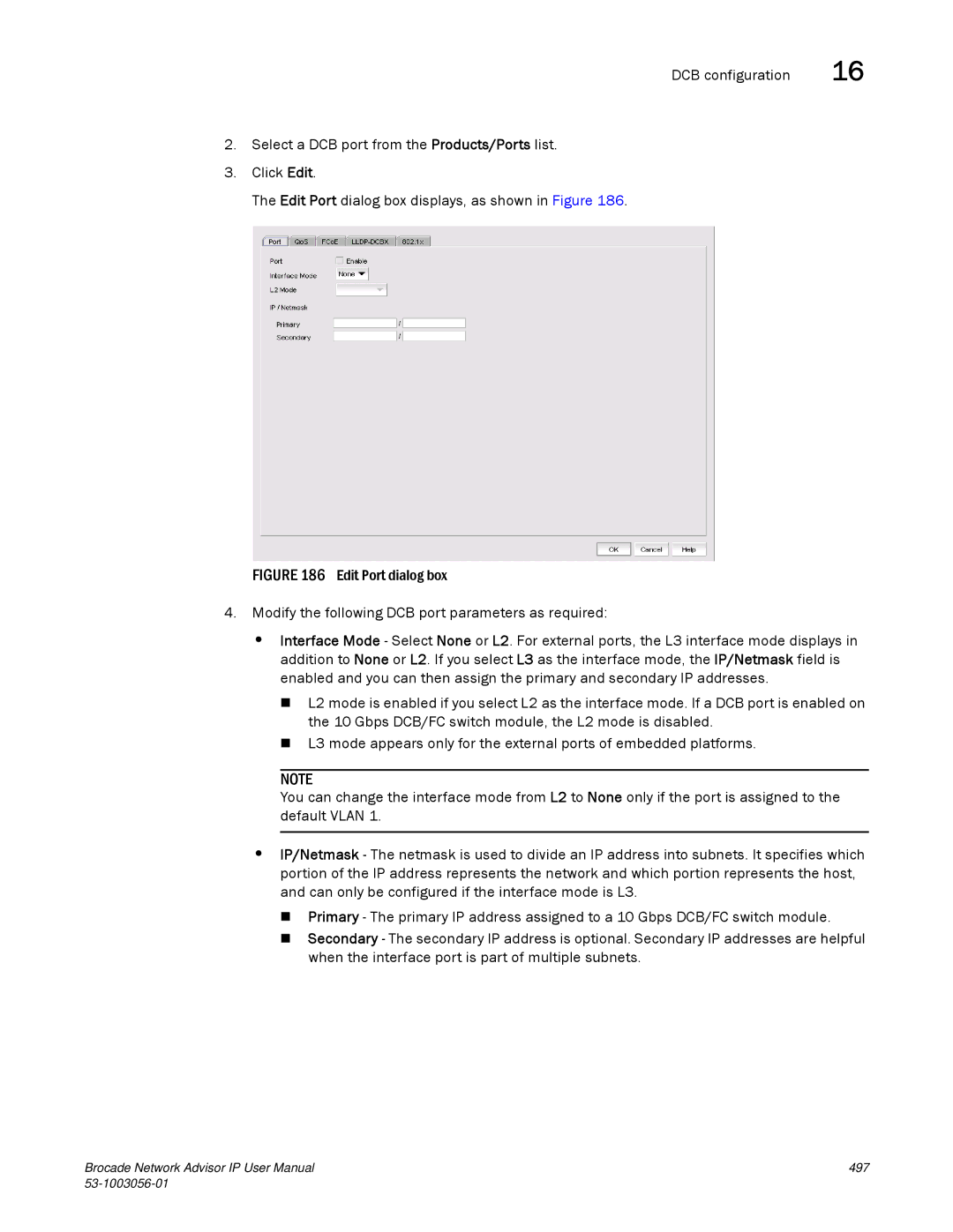
Editing a DCB switch
Editing a DCB port
497
Editing a LAG
499
Enabling a DCB port or LAG
Deleting a LAG
QoS configuration
Creating a DCB map
Strict priority No bandwidth % configuration Allowed
Off
Priority group ID
503
Deleting a DCB map
Editing a DCB map
Assigning a DCB map to a port or link aggregation group
QoS configuration
Creating a Traffic Class map
Editing a Traffic Class map
Select Traffic Class from the Map Type list
Deleting a Traffic Class map
FCoE provisioning
Changing the Vlan ID on the default FCoE map
FCoE provisioning
Select Traffic Class in the Map Type list
Enabling or disabling the FCoE map on the port
Adding a Vlan classifier rule
Vlan classifier configuration
Vlan classifier configuration
Deleting a Vlan classifier rule
Editing a Vlan classifier rule
Deleting a Vlan classifier group
Creating a Vlan classifier group
LLDP-DCBX configuration
Configuring Lldp for FCoE
LLDP-DCBX configuration
515
Deleting an Lldp profile
Editing an Lldp profile
802.1x authentication
802.1x authentication
Assigning an Lldp profile to a port or ports in a LAG
Disabling 802.1x authentication
Enabling 802.1x authentication
Setting 802.1x parameters for a port
16 802.1x authentication
519
Switch, port, and LAG deployment
Deploying DCB product, port, and LAG configurations
Switch, port, and LAG deployment
Deploy to Ports dialog box
522 53-1003056-01
523
Network OS switches in VCS mode
Viewing switches in VCS mode
Network OS switches in VCS mode
Supported VCS platforms
Viewing FCoE parameters on the Network OS switch
Viewing QoS parameters on the Network OS switch
Available Rules
Viewing LLDP-DCBX parameters on the Network OS switch
Vlan Classifiers
Lldp Profiles list
Viewing ports in VCS mode
Viewing the 802.1x parameter on the Network OS switch
Viewing port parameters on the Network OS switch port
Viewing QoS parameters on the Network OS switch port
QoS DCB parameters on the Network OS switch port
QoS-DCB
Viewing FCoE parameters on the Network OS switch port
QoS non-DCB parameters on the Network OS switch port
QoS Non-DCB
Viewing the 802.1x parameter on the Network OS switch port
Viewing LLDP-DCBX parameters on the Network OS switch port
Viewing LAG parameters on the Network OS switch LAG
Viewing LAGs in VCS mode
Re-authentication Interval sec
Port Control
QoS DCB parameters on the Network OS switch LAG
Viewing QoS parameters on the Network OS switch LAG
Type
Minimum Links
QoS non-DCB parameters on the Network OS switch LAG
Viewing FCoE parameters on the Network OS switch LAG
Enable LLDP-DCBX check box
Viewing LLDP-DCBX parameters on the Network OS switch LAG
Real-time performance graph
DCB performance
Generating a real-time performance graph from the SAN tab
DCB performance
Historical performance graph
Generating a real-time performance graph from the IP tab
Generating a historical performance graph
Historical performance report
FCoE login groups
Generating a historical performance report
Historical Performance Graph dialog box displays
539
FCoE login groups
Adding an FCoE login group
Editing an FCoE login group
FCoE login groups Click OK
FCoE Login Group Confirmation and Status dialog displays
Deleting one or more FCoE login groups
Disabling the FCoE login management feature on a switch
Select a group from the Login Groups list and click Delete
Enabling the FCoE login management feature on a switch
Virtual FCoE port configuration
Virtual FCoE port configuration
Viewing virtual FCoE ports
Clearing a stale entry
Select the Virtual FCoE Ports tab
Virtual FCoE Ports tab displays, as shown in Figure
545
546 53-1003056-01
Telemetry
Telemetry overview
Policy-based routing
Viewing existing PBR policies
549
Adding rules to a policy
Adding a new policy
551
Adding policies from saved configurations
Editing a policy
Editing a rule
Deploying a PBR policy on demand
Deleting a policy or rule
Saving a PBR policy deployment
Click OK on the Deploy to Products PBR dialog box
Select Save deployment only
Scheduling a PBR policy deployment
Configuring an hourly deployment schedule
Configuring a one-time deployment schedule
Configuring a daily deployment schedule
Configuring a weekly deployment schedule
Configuring a monthly deployment schedule
Configure Security ACL Accounting
Resetting ACL counters
ACL Accounting
Enabling or disabling ACL accounting
Select the Clear all counters on device check box
Viewing ACL counters
Port Selection Layer 2/3 ACL dialog box displays
Click OK on the Port Selection Layer 2/3 ACL dialog box
560 53-1003056-01
Layer 2 access control list management
Security Management
Security overview
IronWare Layer 2 ACL configuration
Creating a Layer 2 ACL configuration IronWare
Add Layer 2 ACL Configuration dialog box displays
MAC
Click OK on the Add Layer 2 ACL Configuration dialog box
Editing a Layer 2 ACL configuration IronWare
Copying a Layer 2 ACL configuration IronWare
566 53-1003056-01
567
Select the Clear ACL Assignment option
Clearing Layer 2 ACL assignments IronWare
Fabric OS Layer 2 ACL configuration
Creating a standard Layer 2 ACL configuration Fabric OS
DeviceName Layer 2 ACL Configuration dialog box displays
Editing a standard Layer 2 ACL configuration Fabric OS
Copying a standard Layer 2 ACL configuration Fabric OS
Click OK on the Edit Layer 2 ACL Configuration dialog box
Select Extended from the Type list
Creating an extended Layer 2 ACL configuration Fabric OS
572 53-1003056-01
Copying an extended Layer 2 ACL configuration Fabric OS
Editing an extended Layer 2 ACL configuration Fabric OS
574 53-1003056-01
Clearing Layer 2 ACL assignments Fabric OS
Creating a Layer 2 ACL from a saved configuration
Deleting a Layer 2 ACL configuration from the application
Deleting a Layer 2 ACL configuration from the switch
Viewing Layer 2 ACL configuration on a fabric Network OS
Network OS Layer 2 ACL configuration
Viewing Layer 2 ACL configuration on a device Network OS
Viewing Layer 2 ACL configuration on an interface Network OS
Click OK on the Port Selection Layer 2 ACL dialog box
Layer 3 access control list policy
Creating a standard L3 ACL configuration
Add L3 ACL Configuration dialog box displays
Layer 3 access control list policy
Click OK on the Add L3 ACL Configuration dialog box
Creating a L3 ACL from a saved configuration
Editing a standard L3 ACL configuration
Edit L3 ACL Configuration dialog box displays
Click OK on the Edit L3 ACL Configuration dialog box
Creating an extended L3 ACL configuration
Copying a standard L3 ACL configuration
Click OK on the Duplicate L3 ACL Configuration dialog box
Click Duplicate
586 53-1003056-01
L3 ACL Advanced Settings dialog box displays
Editing an extended L3 ACL configuration
Copying an extended L3 ACL configuration
589
Add L3 ACL IPv6 Configuration dialog box displays
Creating an IPv6 L3 ACL configuration
Click OK on the Add L3 ACL IPv 6 Configuration dialog box
Editing an IPv6 L3 ACL configuration
Copying an IPv6 L3 ACL configuration
Deleting a L3 ACL configuration
Assigning a L3 ACL configuration to an interface
Click OK on the DeviceName L3 ACL Configuration dialog box
595
Clearing L3 ACL assignments
Configuring hit statistics
Configuring the ACL configuration type and operations
Configuring L3 ACL advanced settings
599
600 53-1003056-01
3qosp3time-exceeded
Network configuration
Viewing existing networks
To view all existing networks, complete the following steps
Creating a network
Layer 3 access control list policy Click the Networks tab
Editing a network
Deleting a network
Copying a network
Viewing existing network groups
Network group configuration
Review the List of Network Groups table
Creating a network group
To create a network group, complete the following steps
Click the Network Groups tab
To edit a network group, complete the following steps
Editing a network group
To copy a network group, complete the following steps
Copying a network group
Click OK on the Duplicate Network Group dialog box
Service configuration
Deleting a network group
To delete a network group, complete the following steps
Viewing existing services
TCP UDP
Creating a service
Copying a service
Editing a service
Deleting a service
Viewing existing service groups
Service group configuration
Click the Service Groups tab
Review the List of Service Groups table
Creating a service group
To create a service group, complete the following steps
Click Add Add Service Group dialog box displays
To edit a service, complete the following steps
Editing a service group
Copying a service group
To copy a service, complete the following steps
Click OK on the Duplicate Service Group dialog box
Media Access Control MAC filter management
Deleting a service group
Media Access Control MAC filter management
Creating a MAC filter configuration
Add MAC Filter dialog box
Creating a MAC filter from a saved configuration
Editing a MAC filter
Click OK on the MAC Filter Saved Configurations dialog box
Copying a MAC filter
626 53-1003056-01
Assigning MAC filters
Deleting a MAC filter
Clearing MAC filter assignments
Adding a MAC filter configuration to an interface
Security configuration deployment
Security configuration deployment
Deploying a security configuration on demand
Click OK on the Deploy to Products Layer 2 ACL dialog box
Saving a security configuration deployment
Deploy to Product/Ports dialog box
Scheduling a security configuration deployment
Select an ACL in the list and click Edit
Edit Layer 2 ACL Configuration dialog box displays
634 53-1003056-01
635
636 53-1003056-01
Zoning overview
Zoning
Green Zone
Online zoning
Zoning naming conventions
Offline zoning
Configuring zoning
Zoning configuration
Zone database size
Zone database size
Creating a zone
Viewing zone properties
Click New Zone
Zoning configuration
Select Save to Switch from the Zone DB Operation list
Adding members to a zone
Creating a member in a zone
Removing a member from a zone
Click New Member
Renaming a zone
Duplicating a zone
Deleting a zone
Select Configure Zoning Fabric
Enabling or disabling the default zone for fabrics
Customizing the zone member display
Click Zoning Policies
Creating a zone alias
Editing a zone alias
Click New Alias
Removing an object from a zone alias
Renaming a zone alias
Exporting zone aliases
Deleting a zone alias
Click Export Alias
Creating a zone configuration
Click New Configuration
Duplicating a zone alias
Adding zones to a zone configuration
Viewing zone configuration properties
Removing a zone from a zone configuration
Zone Configuration Properties dialog box displays
Click Activate
Activating a zone configuration
Deactivating a zone configuration
Click the Active Zone Configuration tab
Click Deactivate
Deleting a zone configuration
Renaming a zone configuration
Creating an offline zone database
Duplicating a zone configuration
Select Delete from the Zone DB Operation list
Deleting an offline zone database
Refreshing a zone database
Merging fabrics
Select Refresh from the Zone DB Operation list
Select Compare from the Zone DB Operation list
Merging two zone databases
Creating a common active zone configuration in two fabrics
Exporting an offline zone database
Saving a zone database to a switch
You cannot export an online zone database
Select an offline zone database from the Zone DB list
Zoning administration
Importing an offline zone database
Rolling back changes to the offline zone database
To compare two zone databases, complete the following steps
Comparing zone databases
Managing zone configuration comparison alerts
Clearing the fabric zone database
Setting change limits on zoning activation
Finding a member in one or more zones
Removing all user names from a zone database
Select Clear All from the Zone DB Operation list
Select Undo CheckOut from the Zone DB Operation list
Finding zones in a zone configuration
Finding a zone configuration member in the zones list
Finding a zone member in the potential member list
Listing un-zoned members
Listing zone members
Removing an offline device
Replacing zone members
Click OK on the Offline Device Management dialog box
Replacing an offline device by name
Replacing an offline device by WWN
670 53-1003056-01
About port fencing
Port Fencing
About port fencing
Viewing port fencing configurations
673
Thresholds
C3 Discard Frames threshold
Protocol error threshold
Link Reset threshold
Invalid CRCs threshold
Invalid words threshold
State Change threshold
Adding thresholds
Adding a C3 Discard Frames threshold
Adding thresholds
Add C3 Discard Frames Threshold dialog box displays
Port Fencing dialog box
Add Invalid CRCs Threshold dialog box displays
Adding an Invalid CRCs threshold
Add Invalid Words Threshold dialog box displays
Adding an Invalid Words threshold
Adding a Link Reset threshold
Add Link Reset Threshold dialog box displays
Adding a Protocol Error threshold
Select Protocol Error from the Violation Type list
Add Protocol Error Threshold dialog box displays
Add State Change Threshold dialog box displays
Adding a State Change threshold
Assigning thresholds
Avoiding port fencing inheritance
Unblocking a port
Editing thresholds
Editing a C3 Discard Frames threshold
Click OK on the Edit C3 Discard Frames Threshold dialog box
Editing an Invalid Words threshold
Editing an Invalid CRCs threshold
Editing thresholds
Click OK on the Edit Invalid CRCs Threshold dialog box
Editing a Protocol Error threshold
Editing a Link Reset threshold
Click OK on the Edit Link Reset Threshold dialog box
Click OK on the Edit Invalid Words Threshold dialog box
Editing a State Change threshold
Click OK on the Edit Protocol Error Threshold dialog box
Finding assigned thresholds
Viewing thresholds
Viewing all thresholds on a specific Fabric OS device
Removing thresholds from individual objects
Removing thresholds
Removing thresholds from the thresholds table
Removing thresholds
Ficon Environments
Ficon configurations
Configuring a switch for Ficon operation
Planning the configuration
Configuring a switch for Ficon operation
697
Select Discover Fabrics
Configuring the switch
Click Add License
Click Download
701
Configuring an Allow/Prohibit Matrix
Configuring Ficon display
703
Click Analyze Zone Conflicts
Configuring an Allow/Prohibit Matrix manually
Click Manual Allow/Prohibit
Manual Allow/Prohibit dialog box displays, as shown in on
Click OK on the Manual Allow/Prohibit dialog box
Save As/Duplicate dialog box displays, as shown in on
Copying an Allow/Prohibit Matrix configuration
707
Deleting an Allow/Prohibit Matrix configuration
Activating an Allow/Prohibit Matrix configuration
Activating an Allow/Prohibit Matrix configuration
Confirmation message displays, as shown in on
Cascaded Ficon fabric
Changing the Allow/Prohibit Matrix display
Changing window arrangement
Clearing port names
Configuring a cascaded Ficon fabric
Cascaded Ficon fabric
Enabling DLS
Cascaded Ficon fabric merge
713
Merging two cascaded Ficon fabrics
Set up merge options screen displays
Range is form 10 through 500 km. The default is 50 km
Specify the Cable length between switch ports
Resolving merge conflicts
TOV
717
Viewing port groups
Select Configure Port Groups
Port Groups dialog box displays, as shown in on
To view port groups, complete the following steps
To edit a port group, complete the following steps
Swapping blades Click OK
Swapping blades
721
722 53-1003056-01
IP Element Manager
Element Manager overview
Element Manager CLI
Element Manager CLI
Accessing the IP Element Manager CLI
Select Configure Element Manager GUI
Accessing the Element Manager interface
Element Manager interface overview
Element Manager interface overview
Serial #
Switch properties
Port Count
Build Label
727
Properties dialog box Ports tab
Element Manager toolbar
Displaying port properties
Rx Power
Tx Power
Temperature Tx Bias Current
Port Mode
Comparing physical port properties
Comparing physical and virtual port properties
You can compare physical and virtual port properties
Comparing physical and virtual port properties
Status indicator icons
Search
Table capabilities
Real-time performance monitoring
Performance data
Historical performance monitoring
Real Time Graph/Table Historical Graph/Table
Configure dialog box
Configuring Vlan
Resetting port counters
Management Module switchover
Enable or Disable
Changing the standby Management Module to active
MR Switch Over Status dialog box
Switch Fabric Module
Configuring port mirroring
Port mirroring
Port mirroring
Select Configure Port Mirroring
Adding a port to port mirroring
Editing a port in port mirroring
Configuring sFlow in Element Manager
SFlow
Deleting a port from port mirroring
Select Configure Element Manager Web
Accessing the Web Management interface
Web Management interface
Web Management interface
Accessing the IP device front panel
Web Management interface troubleshooting
Select Configure Element Manager Front Panel
Element Manager Front Panel
Configuration repository
Configuration Repository and Backup
Configuration repository
745
Saving the configuration status
747
Comparing product configurations
Viewing the configuration
749
Restoring a configuration
Searching the configuration repository
Exporting a configuration to a text file
Configuration deviation
Viewing configuration deviation status
Change tracking
754 53-1003056-01
Configuration Snapshots tab displays, as shown in Figure
Configuration snapshots
Comparing configuration snapshots
Configuration snapshots
Generating a configuration snapshot report
Viewing the pre- and post-configuration snapshot
Click Save Snapshot
Saving a configuration snapshot
Searching the configuration snaphots
Scheduling a configuration backup
Schedule backup
763
Edit Automatic Configuration Backup dialog box displays
Disabling a backup schedule
Configuration requirements
IP Configuration Wizard
Payloads
Payloads
Payload name Description Product Payloads
DNS
Select Configure Configuration Wizard
Creating a payload configuration
Payload name Description
Interface Payloads
Creating a payload configuration
769
770 53-1003056-01
Don’t Save to Flash or Reload
Save to Flash
Save to Flash and Reload
Configuration dialog box Deployment Schedule pane
773
Modifying a payload configuration
Duplicating a payload configuration
Duplicating a payload configuration
Select a configuration from the Product Configurations list
Modifying a payload configuration
Deploying a payload configuration
Deleting a payload configuration
Deploying a payload configuration
CLI configuration overview
CLI Configuration Management This chapter
Select Configure CLI Configuration
Viewing existing templates
Viewing existing templates
Creating a new product configuration
Product configuration templates
Product configuration templates
To create a new configuration, complete the following steps
780 53-1003056-01
781
CLI Template dialog box Parameters tab
783
CLI Credentials dialog box
Changing product credentials
Importing parameter values into a configuration
Previewing CLI commands Different values for each target
Previewing CLI commands
Same value for each target
Select a row in the Parameters table Click Preview
CLI command guidelines
Copying a product configuration
CLI command guidelines
Editing a product configuration
To test a configuration, complete the following steps
Testing a configuration
Editing the CLI responses properties file
Valid and invalid responses from devices
Successresponsestart
Editing the Network OS CLI responses properties file
Successresponseend
Failureresponseend
Valid and invalid responses from devices
Configuration command response validation
Using a dash character in CLI Configuration manager
Deleting a configuration
Configuration error checking
To delete a configuration, complete the following steps
Deploying a configuration on demand
CLI configuration deployment
Creating a monitoring configuration
Monitoring configurations
796 53-1003056-01
797
Show interface ethernet $portSLOTPORTSlot#/Port#
799
Copying a monitoring configuration
Editing a monitoring configuration
CLI deployment reports
Viewing CLI deployment reports
Select Reports Product CLI
Configuring a one-time deployment schedule
CLI configuration scheduling
Configuring an hourly deployment schedule
Product CLI Report displays
Configuring a weekly deployment schedule
Configuring a daily deployment schedule
Configuring a monthly deployment schedule
CLI configuration scheduling
Configuring a yearly deployment schedule
806 53-1003056-01
Obtaining software files
Image Repository for IP Products
Viewing the list of boot images
Boot image management
Products supporting the image import
Products supporting the image import
Select Configure Firmware Management
Manually importing boot images
Deleting boot images from the Management application
Deploying boot images to products
Viewing the list of software images
Software image management
Manually importing software images
Software image management
Click OK on the Import Software Image dialog box
Automatically retrieving software images from products
Schedule Backup dialog box displays, as shown in Figure
Right-clickConfiguration Schedule Backup
Deploying software images to products
Deleting software images from the Management application
Unified image management
Viewing the list of unified images
Unified image management
Import Firmware Image from File dialog box displays
Importing unified images into the Management application
Click OK on the Manual Import Unified Image dialog box
Deploying unified images to products
Updating unified images
Deleting unified images from the Management application
Complete the following steps
Serial firmware update and activation for NOS devices
Default Vlan
Vlan Management
Vlan Manager
Remote Switched Port Analyzer
Super-aggregated Vlan
Private Vlan
Transparent LAN Support
Configuration requirements for Vlan Manager
Displaying a list of VLANs
Feature VCS FC mode Logical chassis mode Standalone mode
Vlan management in a VCS environment
Vlan Manager tabs
Displaying VLANs in the Vlan view
824 53-1003056-01
Displaying VLANs by products
826 53-1003056-01
Adding or modifying port VLANs
Port VLANs
828 53-1003056-01
Select Configuration Manager Vlan Manager
Adding or modifying dual mode ports
Assigning DCB ports to a Vlan
L2 mode Tagged mode
Adding Vlan properties
832 53-1003056-01
Deleting port VLANs from products
Modifying port Vlan properties
Deleting a port Vlan in Vlan view
Deleting a port Vlan in Product view
Deploying Vlan configurations
Spanning Tree Protocol configuration
Spanning Tree Protocol configuration
Select a Save Configuration option
Configuring STP or Rstp on a port Vlan
IOS Vlan STP, Rstp
Target context STP type
STP, RSTP, Mstp
FOS Vlan Mstp
Deploying an STP configuration on a port Vlan
Configuring Mstp on a product
Adding an Mstp instance
Assigning an Mstp instance to a Vlan
Vlan routing
Managing IP addresses on an SVI
Vlan routing
Deploy IP Configuration dialog box
Vlan routing Click the Deploy now option
Select a Save Configurations option
Mpls Management
Mpls pre-configuration
Mpls licensing
Mpls Licensed and Configured Products group
Mpls overview
Configuring LDP
LSP
Viewing LSP Admin Group information
Select Configure Mpls LSP
Select the Admin Groups tab Figure
Select the Paths tab Figure
Viewing LSP path information
Select the Rsvp LSPs tab Figure
Viewing Rsvp LSP information
Related topics Mpls overview
Viewing saved LSP configurations
LSP
Adding an LSP admin group
Duplicating an LSP admin group
Editing an LSP admin group
Adding an LSP path
Deleting an LSP admin group
You can edit an LSP path by taking the following steps
Editing an LSP path
LSP Delete Path Configuration wizard displays Figure
Duplicating an LSP path
Deleting an LSP path
Configuring advanced Rsvp LSP settings
Admin Groups Selector dialog box
858 53-1003056-01
859
860 53-1003056-01
Rsvp LSP Advanced Settings Fast Reroute tab
Bypass LSP
Editing an Rsvp LSP
Delete Rsvp LSP Configuration wizard displays Figure
Duplicating an Rsvp LSP
Deleting an Rsvp LSP
Duplicating a saved LSP configuration
Editing a saved LSP configuration
Select the saved configuration Click the Edit button
Select the saved configuration Click the Duplicate button
Select the saved configuration Click the Delete button
Deleting a saved LSP configuration
Displaying LSP Topologies
Select Monitor Mpls LSP Topology
LSP right-click options on the Topology View
Mpls Virtual Leased Line VLL overview
868 53-1003056-01
Select Configure Mpls VLL
VLL manager
Viewing VLL instances
Status
VLL Mode
Tag Mode
To view current saved VLL configurations, do the following
Viewing Saved VLL configurations
To add a new VLL instance do the following
Adding or editing a VLL instance
Configuring devices using the VLL Manager
VLL Configuration wizard Port Configuration dialog box
VLL Configuration wizard Deploy Target Actions dialog box
Deploying target actions using the VLL Manager
VLL configuration wizard Deployment Properties
Deploying VLL properties using the VLL Manager
VLL configuration wizard Deployment Schedule dialog box
Scheduling deployment using the VLL Manager
Reviewing the VLL Manager summary
Reviewing the VLL Manager configuration
Editing a VLL instance
Creating a new VLL instance using duplicate
Deleting VLL instances
To edit a VLL instance, do the following
Filtering VLL traffic monitoring
Select Monitor Mpls VLL
VLL Monitor Dialog box displays Figure
VLL
Virtual Private LAN Services Vpls overview
883
Vpls Manager
Select Configure Mpls Vpls
Viewing Vpls instances and peer topologies
Vpls Manager
Endpoint settings PE Devices
Vpls settings
Vpls Manager Peer Topology tab
To view current Vpls configurations, do the following
Viewing Saved Vpls configurations
Adding or editing a Vpls instance
Vpls Configuration wizard Device Configuration dialog box
Configuring devices using the Vpls Manager
Row is added to the Configured Endpoint Settings list
Configuring endpoint settings
Deployment Properties page displays Figure
Deploying target actions using Vpls Manager
Vpls Configuration wizard Deployment Properties dialog box
Deploying Vpls properties using Vpls Manager
Vpls Configuration wizard Deployment Schedule dialog box
Scheduling deployment using Vpls Manager
Creating a new Vpls instance from a duplicate
Reviewing the Vpls Manager summary
Editing a Vpls instance
Deleting a Vpls instance
To edit a Vpls instance, do the following
Filtering for Vpls traffic monitoring
Select Monitor Mpls Vpls
Vpls Monitor dialog box displays Figure
Vcid pools
Select Configure Mpls Vcid Pool
Viewing, creating, and deleting Vcid pools
Vcid pools
Configuring a maintenance association
802.1ag Connectivity Fault Management
802.1ag CFM
Add Maintenance Association dialog box displays
900 53-1003056-01
802.1ag Connectivity Fault Management
Editing a maintenance association
Click Close on the Configure 802.1ag CFM dialog box
Edit Maintenance Association dialog box displays
902 53-1003056-01
903
28 802.1ag Connectivity Fault Management
Adding a MEP to a maintenance association
905
Editing a MEP
907
Viewing the MEPs in a maintenance association
Deleting a maintenance association
Checking the connectivity status of remote MEPs
Sending a loopback message
Click Loopback
Sending a linktrace message
Click Linktrace
Configuring frame delay
915
916 53-1003056-01
VIP Servers
Select Configure Application Delivery VIP Servers
VIP Servers overview
Viewing the VIP Servers
Viewing the VIP Servers
Viewing VIP Server information
Viewing VIP Server information
VIP Servers list
Server port statistics
Enabling or disabling servers or server ports
Enabling servers or server ports
Disabling servers or server ports
Deleting a row from the Server Port Statistics list
Gslb Manager
Global Server Load Balancing
Select Configure Application Delivery Gslb
Viewing the Gslb Manager
To view the Gslb Manager, perform the following steps
Creating a Gslb policy
Gslb policy management
Gslb policy management
To create a Gslb policy, perform the following steps
926 53-1003056-01
Applying metrics on the Metrics tab
Adding a prefix on the Prefix tab
Connection Load Weights
Importing IP addresses from a file
Deleting a prefix from the Prefix list
930 53-1003056-01
Adding a site configuration
Gslb site management
Gslb site management
Adding ServerIron ADX products to the site
Adding a zone configuration
Gslb zone configuration
Gslb zone configuration
Managing zones
Add Hosts dialog box
Adding a host to a zone
Editing the list of IP addresses and weights
Deleting a zone configuration
List of IP Addresses and Weights dialog box displays
Controller configuration
Controller configuration
Controller Configuration tab displays
Creating a new Gslb controller configuration
939
Deploying a controller configuration
Scheduling a deployment
One Time Hourly Daily Weekly Monthly Yearly
SSL certificates
SSL Certificates for ServerIron Products
Accessing SSL certificates on the Certificate View tab
SSL certificate configuration
SSL Certificates dialog box has two tabs
Certificate View tab Figure Product View tab Figure
945
SSL Certificates dialog box Product View tab
Accessing SSL certificates on the Product View tab
Generating a certificate signing request
948 53-1003056-01
949
Related topic
Adding an SSL certificate and key file
Editing an SSL certificate and key file
Viewing SSL certificate details
Duplicating an SSL certificate and key file
Importing certificates and keys from file locations
Importing certificates and keys from products
Exporting certificates and keys
Deploying certificates and keys
Creating key passwords
958 53-1003056-01
Chaining SSL certificates
Appending SSL certificates
960 53-1003056-01
Deleting SSL certificates
962 53-1003056-01
Select Configure Task Scheduler
Editing a deployment configuration
Deployment Manager
Introduction to the Deployment Manager
Duplicating a deployment configuration
Deploying a configuration
Deleting a deployment configuration
Viewing deployment logs
Generating a deployment report
Searching the configuration snapshots
Generating a deployment configuration snapshot report
967
968 53-1003056-01
SAN performance overview
Performance Data
SAN performance overview
SAN performance measures
SAN performance management requirements
Example of default access control list
Example of Snmp
Example of setting Snmp
974 53-1003056-01
Snmp GET
Snmp SET
FCIP-MIB YES
Generating a real-time performance graph
SAN real-time performance data
SAN real-time performance data
Select Monitor Performance Real-Time Graph
Filtering real-time performance data
Real Time Performance Graphs dialog box displays
Open the Real Time Performance Graphs dialog box
Graph display
Performance statistics counters
Exporting real-time performance data
Protocol
Fcip Snmp
HBA, CNA HCM API
Http
FC, GE
HBA, CNA
Type Protocol Source OID value
IP performance monitoring and traffic analysis
IP configuration requirements
IP real-time performance monitoring
Monitoring real-time performance
IP real-time performance monitoring
984 53-1003056-01
Adding products and ports to real-time performance
Removing products and ports from real-time performance
Click Sources from the Real Time Graphs/Tables dialog box
Removing measures from products
Adding measures to products
Select measures Real Time Graphs/Tables dialog box displays
Click Mibs tab in the Available Measures area
Adding measures to ports
Adding collectibles to monitoring
Removing measures from ports
Configuring the performance graph
Configuring the performance graph display
Removing collectibles from monitoring
Show data points graph
Minutes Hours Day
Configuring graph options
Graph Options dialog box Historical Graphs/Tables dialog box
993
Printing a graph
Exporting a graph
Choose Export File Format dialog box displays
Spreadsheet .csv Image .png
IP historical performance monitoring
Displaying historical data collectors
Editing system collectors
IP historical performance monitoring
Name Collector Basics
997
Adding or editing a historical data collector
Enabling a historical data collector
999
1000 53-1003056-01
1001
1002 53-1003056-01
1003
1004 53-1003056-01
Configuring a MIB walk instance
Adding third-party device MIB objects manually
Duplicating a historical data collector
Adding, editing, or duplicating a user-defined expression
Deleting a historical data collector
Duplicating system data collectors
Select Monitor Performance Historical Data Collectors
1007
Complete the following steps to delete an expression
Deleting an expression
Select the Data Monitoring tab
Viewing Historical Graphs/Tables
NetIron Historical Graph display
Select the Collection Status Summary tab
Mouse functions for graphs
Mapping a MIB object to a unit name
MIB data collectors
MIB data collectors
To map a MIB name, use the following format
Creating a custom report
IP Custom performance reports
IP Custom performance reports
Complete the following steps to create a report
1015
Time Settings Sampling Granularity
1017
Click the Identification tab
Exporting an Snmp Monitor report
Interpreting the Snmp Monitor report
IP sFlow configuration
Configuring sFlow
IP sFlow configuration
IP sFlow configuration Click Next
Interface Payload sFlow Settings dialog box displays
Interface Speed Sampling rate
Product Payload SFlow Destination dialog box displays
Click Next
Select the Report Definitions tab
Creating custom sFlow reports
IP sFlow configuration Select the Product & Port tab
1026 53-1003056-01
1027
IP sFlow configuration Select the Layer 3 & 4 tab
Add Report Definitions dialog box, User Identification tab
Select the User Identification tab
Add Report Definitions dialog box, Time Settings tab
Select the Result Settings tab
Add Report Definitions dialog box, Result Settings tab
1033
Select Monitor Traffic Analysis Custom Reports
Scheduling custom sFlow reports
1035
1036 53-1003056-01
Device-level configuration requirements
IP Traffic analyzer monitoring and sFlow reports
Suspending a custom sFlow report schedule
Displaying sFlow monitoring reports
802.1X configuration requirements
IP Traffic analyzer monitoring and sFlow reports
Select Monitor Traffic Analysis Monitor sFlow
Report list
Selecting a report
Measure list
Save and close the ipconfig.properties file
Interpreting an sFlow traffic report
This field shows the date and time the report was requested
Viewing top MAC talkers
Category list, select L3/L4 Reports
Viewing top Vlan talkers
Viewing all IPv4 Layer 3 or Layer 4 Top Talkers
Viewing all Layer 3 and Layer 4 traffic
Reports list, select IPV4 Next list, select TCP
Viewing IPv4 top TCP talkers
TCP
Viewing IPv4 top UDP talkers
Viewing IPv4 top Icmp talkers
Category list, select L3 or L4 Reports
Icmp
Viewing IPv6 Top Talkers
Viewing IPv4 Others
Viewing other Layer 3 or Layer 4 Top Talkers
Defining invalid TCP packet combinations
Enabling and viewing TCP reports
RST-SYN RST-FIN RST-PSH RST-URG FIN-SYN
Complete the following steps to change these combinations
Displaying the invalid TCP Flags report
Valid TCP flags report
Type list, select Invalid TCP Flags
Viewing VCS fabric Top Talker reports
Viewing BGP paths report
IP traffic accounting
Troubleshooting sFlow reports
IP traffic accounting
Select Monitor Traffic Analysis Traffic Accounting
1055
1056 53-1003056-01
Frame Monitor
Frame Monitor
Frame types
Scsi
Scsi RW
Frame Monitoring requirements
Creating a custom frame monitor
Frame Monitor Configuration Status dialog box
Assigning a frame monitor to a port
Editing a frame monitor
Removing a frame monitor from a port
Finding frame monitor assignments
Removing a frame monitor from a switch
1064 53-1003056-01
Power center overview
Power Center
Select Monitor Power Center
Data monitoring
Viewing PoE data for products
To view PoE data for a port, complete the following steps
Viewing PoE data for ports
To filter port details, complete the following steps
Filtering port details
Viewing attached device properties
1070 53-1003056-01
To view a PoE chart, complete the following steps
Viewing PoE charts
1072 53-1003056-01
1073
Refreshing PoE data
Configuring automatic data refresh
PoE power on demand
Powering up PoE-capable ports on demand
PoE power on demand
Powering down PoE-capable ports on demand
Scheduling an power up deployment
Schedule PoE power deployment
Schedule PoE power deployment
1079
1080 53-1003056-01
Configuring a yearly deployment schedule
Scheduling a power down deployment
Updating a power deployment schedule
Scheduled Ports ScheduleName dialog box displays
Click Show Ports
Deleting a power deployment schedule
PoE thresholds
Adding a PoE product threshold
PoE thresholds
PoE Consumption Consumption %
PoE Allocation
Adding a PoE port threshold
Port allocation Port consumption Port consumption %
Thresholds dialog box Choose one of the following measures
To view PoE thresholds, complete the following steps
Viewing PoE thresholds
Updating a PoE threshold
To update a PoE threshold, complete the following steps
To disable PoE thresholds, complete the following steps
To enable PoE thresholds, complete the following steps
Enabling PoE thresholds
Disabling PoE thresholds
Viewing PoE performance
Monitoring real time power performance on products
Deleting PoE thresholds
Viewing PoE performance
1094 53-1003056-01
1095
Monitoring real time power performance on ports
1097
1098 53-1003056-01
Policy monitor overview
Policy Monitor
Policy monitor overview
Fabric policy monitors
Switch and router policy monitors
1102 53-1003056-01
Host policy monitors
1104 53-1003056-01
Next Run Next time the policy will run using the format
Preconfigured policy monitors
Management policy monitor
Frequency Weekly
Viewing policy monitor status
Viewing existing policy monitors
Select Monitor Policy Monitor
Adding a policy monitor
1109
Add Policy Monitor dialog box, Switch/Router Checks tab
1111
Add Policy Monitor dialog box, Hosts Checks tab
Policy monitor scheduling
Configuring a one-time policy monitor schedule
Configuring a daily policy monitor schedule
Configuring an hourly policy monitor schedule
Configuring a weekly policy monitor schedule
Configuring a monthly policy monitor schedule
Deleting a policy monitor
Editing a policy monitor
Configuration rules
Viewing a predefined configuration rule
Predefined configuration rules
Viewing configuration rule details
Configuration rules Port Profile Interface Rule expressions
Add Configuration Rule dialog box displays Figure
1118 53-1003056-01
1119
Click Cancel on the Add Configuration Rule dialog box
Adding a configuration rule
Click OK on the Add Configuration Rule dialog box
Duplicating a configuration rule
Editing a configuration rule
Click the Switch/Router Checks tab
Click Add Configuration Rule
Importing a configuration rule
Exporting a configuration rule
Deleting a configuration rule
Click OK on the Edit Configuration Rule dialog box
Viewing predefined configuration conditions
Adding a configuration condition
Add Configuration Rule dialog box displays
Add Condition dialog box displays Figure
Select Add Condition
Selecting a product
Duplicating a configuration condition
You cannot edit a predefined configuration condition
Editing a user-defined configuration condition
Predefined conditions
Configuration rules Predefined conditions
Policy Monitor dialog box displays Click Add
Viewing a predefined configuration block
Configuration rules Add Monitor dialog box displays
Adding a configuration block
Select Add Block
Add Block dialog box displays Figure
Select the Switch/Router Checks tab
Duplicating a configuration block
You cannot edit a predefined configuration block
Editing a user-defined configuration block
Deleting conditions and blocks
Predefined blocks
Click Delete Click Yes on the confirmation message
Running a policy monitor
Viewing a policy monitor report
Viewing a policy monitor report
1137
Click Export File Download dialog box displays Click Save
Exporting a policy monitor report
Viewing historical reports for a policy monitor
Viewing historical reports for all policy monitors
Policy Monitor dialog box displays
Click History
Viewing historical reports for a policy monitor
Fault management overview
Fault Management
Restrictions
Event notification
Supported IP address types
Event Purging
1143
Setting up basic event filtering
Defining filters
Defining filters
Click Advanced
Setting up advanced event filtering
1146 53-1003056-01
Snmp traps
Select Monitor Snmp Setup Product Trap Recipients
Adding a trap recipient to one or more switches
Snmp traps
Snmp Trap Recipients dialog box, shown in , displays
Select Monitor Snmp Setup Trap Forwarding
Removing a trap recipient from one or more switches
Snmp trap forwarding
Snmp Trap Forwarding dialog box, shown in , displays
Adding a trap destination
Select the Enable trap forwarding check box
Adding a new trap filter
1152 53-1003056-01
Event reception
Do not accept Snmp v1/v2c traps
Event Reception dialog box, shown in , displays
Accept Snmp v1/v2c traps with any community string
Accept Snmp v1/v2c traps with only these community strings
Snmp traps Snmp security and authentication
Privacy protocol Authentication Result Credential type
Adding an Snmp v3 credential
Importing a new MIB into the Management application
Adding an Snmp v1 or v2c community string
Trap customization
Registering traps
Unregistering a registered trap
Customizing a registered trap definition
Click the Registered button
Snmp informs
Reverting the customization of a registered trap to default
Enabling or disabling Snmp informs
Select a product group from the Fabric / Products list
Adding a syslog recipient
Syslogs
Removing a syslog recipient
Syslogs
To remove a syslog recipient, complete the following steps
Select the Enable syslog forwarding check box
Select Monitor Syslog Configuration Syslog Forwarding
Adding a syslog forwarding destination
Syslog Forwarding dialog box, shown in , displays
Adding a syslog filter
1165
Snort message forwarding
Event action definitions
Creating an event action definition
Select Monitor Event Processing Event Actions
Event action definitions
Selecting an event for an event action
1168 53-1003056-01
Configuring varbind filters
Sources pane of the Add Event Action dialog box
Selecting source address products and ports
Click Next to advance to the Sources pane
Configuring event action policies
Editing event actions
1174 53-1003056-01
1175
Acknowledging special events
Special events handling
1177
Configuring event action e-mail settings
Modifying an event action definition
Click Cancel to cancel the operation
Deleting an event action definition
Configuring event actions for Snort messages
Pseudo events
Click the Import Snort Rule button
Import Snort Rule File dialog box displays, shown in Figure
Creating pseudo event definitions
Displaying pseudo event definitions
Select Monitor Event Processing Pseudo Events
Pseudo Events dialog box, shown in , displays
Setting pseudo event policies
Filtering pseudo event traps
1185
Deleting a pseudo event definition
Editing a pseudo event definition
Adding a pseudo event on the escalation policy
1188 53-1003056-01
Adding a pseudo event on the resolving policy
1190 53-1003056-01
Adding a pseudo event on the flapping policy
1192 53-1003056-01
Event custom reports
Defining report settings
Event custom reports
Select Reports Event Custom Reports
Defining the report identity
1196 53-1003056-01
To filter a report definition, complete the following steps
Filtering a report definition
Add/Edit Report Definition dialog box Filter tab
Add/Edit Report Definition dialog box Product tab displays
Filtering report events by date and time
1200 53-1003056-01
Editing a report definition
Event custom report schedules
Deleting a report definition
Event custom report schedules
Adding or editing an event report schedule
One Time
Viewing event logs
Event logs
Copying part of a log entry
Event logs
Exporting the entire log
Copying an entire log entry
Mailing all event details from the Master Log
Mailing selected event details from the Master Log
Displaying event properties from the Master Log
Event logs Event Properties
Click Close to close the Event Properties dialog box
Event Field Description
Copying the entire Master Log
Copying part of the Master Log
Exporting the Master Log
Select Table Copy Table
Filtering events in the Master Log
‘unnamed’ filter
Editing a Filter
‘none’ filter
Duplicating a Filter
Deleting a Filter
Select Configure Packet Capture Pcap
Configuring packet captures
Configure Pcap dialog box, shown in , displays
Packet Capture Pcap
1214 53-1003056-01
Technical Support
Server and client support save
Capturing Server and Client support save data
Capturing Server support save data
Capturing Client support save data
Server and client support save
Client support save using a command line interface
Scheduling technical support information collection
Device technical support
Device technical support
Click the Schedule tab
Select the Enable scheduled Technical Support Data check box
1221
Click OK on the Technical SupportSave dialog box
Starting immediate technical support information collection
Click the Generate Now tab, if necessary
Field Description
Click Close on the Technical SupportSave Status dialog box
Firmware Type
Progress
Viewing the technical support repository
Type Default location Default naming convention
Click OK on the Technical Support Repository dialog box
Saving technical support information to another location
Available SupportSave
Mail button
Mailing technical support information
Select the file you want to delete in the table Click Delete
Deleting technical support files from the repository
1229
1230 53-1003056-01
Reports overview
Reports
Viewing IP reports
Browser requirements
Exporting IP reports to e-mail recipients
Exporting and saving IP reports to a file
Select Export as Html Select Export as CSV
Select E-mail as Html Select E-mail as CSV
IP Wired Products report
IP report contents
IP Wired Products report
Detailed Product Report
Export button
Stacking Units
Realtime
Stacking Port
Modules
IP Addresses
Physical Ports
Cluster Peer MCT
GRE Tunnels
Controller Cluster
AP List Count
Detailed Cluster Report
System Information
System Name values
Nodes
IP Module report
FC Ports
Physical Media
IP Port VLANs report
IP Layer 3 Vlan report
Field/ComponentDescription
IP Subnet report Layer 3 Vlan report fields and components
IP Subnet report
MAC Address report
IP Address report
IP Address report
Port Name
IP Physical Ports Realtime report
IP Stacking Ports Realtime report
IP Physical Ports Realtime report
IP Physical Media Realtime report
IP Physical Media Realtime report
Viewing a deployment report
IP Deployment reports
IP Deployment reports
Select Reports Deployment
Reports Template Manager overview
Preconfigured reports
User-defined reports
Reports Template Manager overview
Accessing the Report Template Manager
Select Reports Report Manager
Report Template Manager dialog box displays Figure
Viewing a report
Importing a report template
Exporting a report template
Deleting reports
Report content and functions
Product Count
Products List report
IP address of the product
Displayed for products that support stacking
Physical port information for each port on the product
Product Report
Cluster
Ports Tx/Rx Ratio report
Device Name
Summary table Location
Detailed Product Report
Total Received MB
Low Traffic Ports report
Max Tx Utilization %
Max Rx Utilization %
Exporting data from the report
Application menus
Menu Command Command Options
This appendix
Dashboard main menus
IP main menus
Command Command Options
IP main menus
Edit Menu
Discover Menu
Element Manager. Select to configure a selected device
Configure Menu
Lsan Zoning Device Sharing. Trial and Licensed version
Monitor Menu
Reports Menu
IP shortcut menus
IP shortcut menus
Tools Menu
IP shortcut menus IP Subnet
Component Menu/Submenu Commands Comments
IronWare device
Launches the Real-Time Graphs / Tables dialog box
L2 ACL
DCB
VCS/VDX
Third-party device
1273
1274 53-1003056-01
IP Call Home Event
Call Home Event Tables
Network OS Call Home Event
Event reason code FRU code/Event type Description Severity
Call Home Event Tables Network OS Call Home Event
Product status events
Event Categories
Product audit events
Security events for FC devices
Security events
Security events for IP devices
Security events
Management server events
User action events
IP Performance monitoring events
Product events
Product events
Trap name
IP Performance monitoring events
About user privileges
User Privileges
Privilege Description No Privilege Read-Only Read/Write
About user privileges Application privileges and behavior
Event Notification Setup button in the Users dialog box
Setup Mail server used to Send e-mail Disables Event
Registration
Options command
Forwarding dialog box Monitor menu Event Storage option
Syslog Registration
Enables the Security L2
Management command
Update and OK
Performance Graphs dialog box and enables all controls
Policy monitors Command on the Monitor Menu
Disables Policy Monitor Enables Policy Monitor
Configure Switch Replicate menu
Logs menu
Server Options menu
View Repository Technical Support menu Repository commands
SupportSave, Upload Repository command Upload Failure Data
Capture, and View
Monitor Technical
1291
Zoning
Cancel and Help buttons
Compare/Merge dialog
Compare and Export
Compare/Merge dialog Zone Config tab
Switch, Activate
Edit Limits command
Lsan Zoning Device
Zoning Scope list does
IP CLI
About user privileges IP privileges and behavior
Filter
IP L3 ACL
IP Mpls Vpls
IP Mpls VLL
IP MPLS- LSP
Profile tab
About Roles and Access Levels
About Roles and Access Levels IP privileges and behavior
Application Features and Role Access Levels
1299
IP Mpls LSP
Device Properties
Viewing SAN device properties
Viewing Fabric properties
Viewing SAN device properties
Viewing SAN device properties Fabric properties
Click OK on the FabricName Properties dialog box to close
Viewing SAN device properties Device properties
Remote Switch Name
Preshared key configured
Remote Switch IP
Remote Switch WWN
Viewing Storage properties
ICL
Select Edit Properties
Viewing SAN device properties
Viewing iSCSI Properties dialog box
Digest Error Count
Command Descriptor Block Count
ISCSI Service
ISNS Service
Viewing port properties
Additional Port Info
Class of Service
Address
Active FC4 Types
Viewing SAN device properties Port properties
ISCSI button
Long Distance Setting
ISCSI Capable
Locked Port Type
Troubleshooting list
Symbolic Name
Port Speed Gb/s
Port State
Viewing IP device and port properties
IP device properties
IP device properties Port properties
User Port #
Config Mode
VCS Mode
Detailed Report button
Alias
IP device properties
Access Points tab
Profile Mode
Port Profiles tab
Show list
Transceiver Temperature
Connected switch \ Port
Chassis-Power Supply section of Detailed Report
Device MAC
Viewing VCS fabric properties
Access Gateway Mode
Licensed Features
Nodes tab
Fabric Status
VLANs
MAC Count
Domain Count
Associated MACs list
Native VLAN/VLAN
IP device properties
1324 53-1003056-01
FC Ports properties Identifier The identifier of the port
Host properties
Host properties
SFP/Port Optics
Field Description
Viewing adapter port properties
Host properties Adapter port properties
Adding a property field
Properties customization
Properties customization Adapter port properties
Click OK to close
Deleting a property field
Editing a property field
Editing a property field directly
Properties customization
Regular Expressions
Characters
Construct Matches
Character classes
Regular Expressions Characters
Predefined character classes
Posix character classes US-ASCII only
Java.lang.Character classes simple java character type
Regular Expressions Posix character classes US-ASCII only
Classes for Unicode blocks and categories
Boundary matches
Reluctant quantifiers
Regular Expressions Greedy quantifiers
Possessive quantifiers
Logical operators
Special constructs non-capturing
Regular Expressions Back references
Regular Expressions
CLI Templates
CLI Templates
HyperEdge Stack Disable
HyperEdge Stack Enable
HyperEdge Stack Port Creation
HyperEdge Stack Port Deletion
IronWare OS Configure L3-Access-List
IronWare OS Enable Web Element Manager
CLI Templates HyperEdge Stack Trunk Deletion
HyperEdge Peri Port Creation
MCT Cluster Creation
CLI Templates IronWare OS Configure L2-Access-List
MCT Cluster Deployment
MCT Cluster Undeployment
Mpls Core Interface Configuration
Mpls Loopback Interface Configuration
CLI Templates MCT Cluster Deletion
MCT Client Creation
Network OS Configure CRC Align Errors Monitor
CLI Templates Mpls Endpoint Configuration
Network OS Associate MAC to Port Profile
Ampp
CLI Templates Network OS Configure Extended L2 Access List
Network OS Configure Inter Frame Gap Violation Fencing
Network OS Configure Inter Frame Gap Violation Monitor
Network OS Configure RX Symbol Errors Monitor
Network OS Configure Standard L2 Access List
Network OS Create CoS Mutation Map
Network OS Create Port Profile
CLI Templates Network OS Create Lldp Profile
Network OS Create Traffic Class Map
Network OS Create Vlan Classifier Group
Network OS Update QoS on Port Profile
Network OS Update ACL on Port Profile
Network OS Update Vlan on Port Profile
CLI Templates Network OS Create Vlan Classifier Rule
Private Vlan Delete Pvlan configuration from Vlan
CLI Templates Private Vlan Configure Vlan as a Pvlan
Private Vlan Configure Pvaln mode in L2 interface
Private Vlan Add native Vlan mode to Pvlan trunk
Private Vlan Delete Pvlan associations from host port
Private Vlan Delete Pvlan mapping from promiscuous port
Private Vlan Delete Pvaln associations from trunk port
$PRIMARYVLANIDINTEGER $SECONDARYVLANIDINTEGER
VRF Maximum routes configuration for IPV4 Address Family
VRF Route Distinguisher Configuration
VRF Route Targets Export and/or Import Configuration
VRF Delete Route Targets Export and/or Import Configuration
IronWare OS Vlan Enable Spanning Tree Protocol on IOS Vlan
IronWare OS Vlan Configure virtual routing interface
CLI Templates VRF Display VRF Information
IronWare OS Vlan Remove interfaces from Vlan as untagged
Network OS Vlan Native Vlan Configuration
Network OS Vlan Layer2 Switch Port Configuration
Network OS Vlan Vlan Interface Creation
Network OS Vlan Vlan Interface Deletion
Network OS Vlan Access Interface Configuration
Network OS Vlan Disable Access Interface Configuration
Network OS Vlan Enable Spanning Tree Protocol on NOS Vlan
1356 53-1003056-01
Troubleshooting
Browser troubleshooting
Application Configuration Wizard troubleshooting
Configuration backup and restore troubleshooting
Client browser troubleshooting
Element Manager troubleshooting
Client browser troubleshooting
Firmware download troubleshooting
Firmware download troubleshooting
Sw0FID128admin sshutil delknownhost
Launch Client troubleshooting
Launch Client troubleshooting
Select Start Settings Control Panel Java
Master Log and Switch Console troubleshooting
Master Log and Switch Console troubleshooting
Unix operating systems
Patch troubleshooting
Patch troubleshooting
Click the Global Settings tab
Select Discover IP Products
Professional edition login troubleshooting
Server troubleshooting
Professional edition login troubleshooting
Server Management Console troubleshooting
Server Management Console troubleshooting
Management console errors
Supportsave troubleshooting
Supportsave troubleshooting
Select Properties
Wireless troubleshooting
Technical support data collection troubleshooting
Technical support data collection troubleshooting
Problem Master log warning message
Zoning troubleshooting Wireless troubleshooting
Zoning troubleshooting
Zoning troubleshooting
Database Fields
Achcallcenterconfig
Database tables and fields
Achcallcenter
Acheventfiltermap
Database tables and fields Achevent
Achfilter
Achinfo
Adapterportconfigproperty
Adapterportconfigdetails
Adapterdriverfiledetails
Aordevicegroupmap
Aorfabricmap
Aordevicemap
Aorhostmap
Aorinmportgroupmap
Availableflyoverproperty
Birtreportparameter
Birtreportruntemplate
Bootimagedrivermap
Birtreportscheduleconfig
Bootimagefiledetails
Database tables and fields Birtreportruntemplate
Bootlunsequence
Database tables and fields Bootimagefiledetails
Bootlunsequencedetail
Capability
Database tables and fields Card
Cedapplication
Cardcapability
Cedapplicationmember
Ceduserpreference
Ceeport
Cfgbackuparchive
Database tables and fields Cfgbackuparchive
Changelog
Clitemplate
Clientview
Database tables and fields Clitemplate
Clientviewmember
Clientviewcolumn
Clientviewmemberhost
Cluster
Cnaethportconfig
Cnaethport
Cnaproductconnectivity
Database tables and fields Cnaethportconfig
Cnaport
Collector
Collectormibobjectentry
Configblock
Collectorsnmpexpressionentry
Collectortargetentry
Coreswitch
Configcondition
Database tables and fields Coreswitch
Coreswitchchecksum
Coreswitchcapability
Coreswitchcollection
Coreswitchdetails
Database tables and fields Coreswitchdetails
Cryptohost
Cryptolun
Database tables and fields Cryptolun
Cryptoswitch
Cryptotargetcontainer
Database tables and fields Cryptoswitch
Database tables and fields Cryptotargetcontainer
Customfavoritesobjectlist
Dashboard
Dashboardcanvas
Database tables and fields Dashboard
Dashboardcanvaspreference
Dashboardprovider
Dashboardwidget
Defaultfavorites
Database tables and fields Dashboardwidget
Dashboardwidgetpreference
Database tables and fields Defaultfavorites
Defaultwidgetpreference
Deploymentconfiguration
Database tables and fields Deploymentconfiguration
Deploymenthandler
Deploymentproductstatus
Database tables and fields Deploymentproductstatus
Deploymentreporttemplate
Deploymentstatus
Device
Deploymenttargetmap
Database tables and fields Device
Tacpasswordreadonly
Tacpasswordportcfg
Tacpluspasswordportcfg
Tacpluspasswordreadonl
Trapregistered
Licensedfeatures
Portcount
Mplsmanagestate
Productfamily
Isdcbswitch
Netconftransport
=SSH =HTTPS =WINGHTTPS Poecapable
Wirelesstype
Isprincipalswitch
Vcsid
Vcslicensed
Deviceenclosure
Deviceconnection
Database tables and fields Deviceenclosure
Devicefdmidetails
Deviceenclosuremember
Database tables and fields Devicefdmidetails
Devicegroup
Devicegroupentry
Database tables and fields Devicegroup
Devicemacgroupmapping
Devicenode
Deviceport
Database tables and fields Devicenode
Deviceportmacaddressmap
Deviceportgigeportlink
Encryptionengine
Diskusage
Encryptiongroup
Database tables and fields Encryptionengine
Database tables and fields Encryptiongroup
Encryptionkmipparameters
Encryptiongroupmember
Encryptiontapepool
Ethernetcloud
Ethernetisl
Database tables and fields Ethernetisl
Event
Eventcallhome
Database tables and fields Event
Eventcategory
Eventdescription
Eventfwdfilter
Eventdetails
Database tables and fields Eventfwdfilter
Eventinstance
Eventmodule
Eventnotification
Eventorigin
Eventpolicy
Eventpolicysourceentry
Database tables and fields Eventpolicy
Eventrule
Database tables and fields Eventpolicysourceentry
Eventprocessormap
Fabric
Database tables and fields Eventrule
Eventruleaction
Database tables and fields Fabric
Fabriccollection
Fabricchecksum
Fabricdiscoverypolicy
Database tables and fields Fabriccollection
Fabricdiscoverypolicyrule
Fabricmember
Favorites
Fabricthresholdsetting
Database tables and fields Fabricmember
Fabricvcsclustermap
Database tables and fields Favorites
Fcipcircuitportmap
Fcipporttunnelmap
Fciptunnel
Database tables and fields Fciptunnel
Fciptunnelcircuit
Database tables and fields Fciptunnelcircuit
Securityflag
Mismatchedconfigurations
Circuitstatus
Circuitstatusstring
Fciptunnelperformance
Featureeditionmap
Feature
Featuresusage
Fcoedevice
Database tables and fields Featuresusage
Ficondeviceport
Firmwarefiledetail
Firmwareswitchdetail
Foundrydevice
Foundrymodule
Foundryphysicaldevice
Database tables and fields Foundrymodule
Foundryphysicalport
Fporttrunkgroup
FRU
Ftpserver
Database tables and fields FRU
Generatedreport
Database tables and fields Generatedreport
Gigeport
Gigeportstats
Gigeportethernetcloudlink
Globalvlan
Gretunnelinterface
HBA
Hacluster
Database tables and fields HBA
Hbanodemap
Hbaport
Operatingtopology
Switchip
SUPPORTEDFC4TYPES
Supportedcos
Hbaportdetail
Database tables and fields Hbaportdetail
Hbaportfcoedetails
Hbaportdeviceportmap
Database tables and fields Hbaportfcoedetails
Hbaremoteport
Hbaremoteportlun
Database tables and fields Hbaremoteport
Healthstatus
Hbatarget
Healthtargetstatus
Hostdiscoveryoption
Database tables and fields Hostdiscoveryoption
Hostdiscoveryreqgroup
Hostdiscoveryrequest
Hypervvirtualmachine
Database tables and fields Hostdiscoveryrequest
Hypervvmhbaportmap
IFL
Interface
Interfacedeploymentconfig
Database tables and fields Interface
Ipdevicelicense
Database tables and fields Ipdevicelicense
Ipinterface
Ipportgroup
Ipsubnetvlan
Iproute
Ipxnetworkvlan
ISL
Targetswitchportid
Sourceswitchportid
Database tables and fields ISL
Islconnection
Masterconnectionid
Isltrunkgroup
Sourcemasterport
Targetmasterport
L2ACCESSCONTROLENTRY
Isltrunkmember
Keyvault
L2ACCESSCONTROLLIST
Database tables and fields L2ACCESSCONTROLENTRY
L2ACLDEVICEDEPLOYMAP
L2ACLINTERFACEDEPLOYMAP
L2NEIGHBOR
Database tables and fields L2ACLINTERFACEDEPLOYMAP
L3ACLDEVICEDEPLOYMENTMAP
L3ACLINTDEPLOYMENTMAP
LAG
Database tables and fields L3ACLINTDEPLOYMENTMAP
Lagmember
Lastconfigupdatetime
Database tables and fields Lagmember
Launchincontextmodule
License
Database tables and fields Launchincontextmodule
Licensedowngradedetails
Licensedfeature
Licensefeaturemap
Database tables and fields Licensedowngradedetails
Licenserule
Lock
Lsantagconfig
Lsandevice
Lsanproxydevice
Lsanzone
Lsanzonedbconfig
Lsanzonemember
Mctclient
Macfilterdevdeploymentmap
Database tables and fields Macfilter
Macfilterintdeploymentmap
Macgroup
Mapsevent
Macgroup
Macgroupmember
Managedelement
Database tables and fields Mapsevent
Mapseventdetails
Mapseventcauseaction
Mapspolicy
Marchingants
Measure
Module
Messagerecipient
Migrationhistory
Database tables and fields Module
Mplsadmingroupinterfacerelation
Mplsadmingroup
Mplslsp
Moduleslotpresent
Mplspath
Mplspathhop
Mplsrsvplsp
Mplsrsvplspadmingroupcontainer
Mplsrsvplspadmingroup
Database tables and fields Mplsrsvplsp
Mplsrsvplspactuallyroutedhop
Mplsrsvplspparameters
Mplsrsvplspfrrparameters
Database tables and fields Mplsrsvplspparameters
Mplsservice
Mplsrsvplsppath
Mplsrsvplsptunnelresource
Database tables and fields Mplsservice
Mplsservicedevicerelation
Mplsserviceendpointrelation
Mplsservicepeerrelation
Database tables and fields Mplsserviceendpointrelation
Mrpring
Mrpringdevice
Database tables and fields Mrpringdevice
Networkvlan
N2FPORTMAP
Networkscopetype
Nicprofile
Npflowdefinition
Database tables and fields Nportwwnmap
Database tables and fields Npflowdefinition
Npsubflow
Ouiguesseddevicemap
Pbrinterfaceconfig
Passwordhistory
Ouivendor
Perfcollector
Pbrrule
Pbrpolicy
Pbrnexthop
Pbrruleacllist
Database tables and fields Pbrruleacllist
Phantomport
Physicaldevice
Physicalinterface
Database tables and fields Physicaldevice
Pmcollectortargetsetting
Pmcollectormeasuresetting
Database tables and fields Physicalinterface
Physicalport
Database tables and fields Pmcollectortargetsetting
Pmcollectortimeseriesmapping
Pmdashboardwidget
Pmdatacollector
Database tables and fields Pmdashboardwidget
Pmmeasure
Database tables and fields Pmdatacollector
Pmstatsagingpolicy
Pmwidgetmeasuretypeentry
Pmwidgetmeasuretype
Pmwidgetmonitortype
Pmwidgettargetentry
Pmwidgettopncollectorentry
Database tables and fields Pmwidgettimeseriesentry
Pmwidgetuserentry
Poethreshold
Poethresholdevent
Database tables and fields Poethreshold
Policyrule
Policyrulemap
Portbottleneckconfig
Portbottleneckstatus
Portcommissioncimomserver
Database tables and fields Portcommissioncimomserver
Portfencingpolicy
Portfencingpolicymap
Database tables and fields Portfencingpolicymap
Portprofile
Portprofiledomain
Portprofileinterfacemap
Portprofiledomainmap
Portprofilemacmap
Portprofileqosmap
Portprofilevlanmap
Portprofileqospfcmap
Portvlan
Privilege
Database tables and fields Portvlan
Productapp
Qrtzblobtriggers
Protocolvlan
Qrtzcalendars
Qrtzcrontriggers
Qrtzjobdetails
Qrtzlocks
Qrtzjoblisteners
Qrtzpausedtriggergrps
Qrtzsimpletriggers
Database tables and fields Qrtzschedulerstate
Qrtzjtriggerlisteners
Qrtztriggers
Raslog
Recoverycardgroupmapping
Querybaseddevicegroup
Quorumcardgroupmapping
Reporttemplate
Reporttype
Reportdrilldowntemplate
Resourcefabricmap
Resourcehostmap
Role
Roleprivilegemap
Ruleblockmap
SAN
Rulelogicalexpressionmap
Sanconnection
Scomhost
Database tables and fields Sanconnection
Securitypolicy
Selectedflyoverproperty
Sensor
Sensorid
Currentreading
Sflowhoursummary
Sflowcheckpoint
Outpriority
Inpriority
Srcmac
L3SRCADDR
Sflowminutebgp
Sflowiprouteinfo
Sflowminutebgpslnum
Database tables and fields Sflowminutebgp
SFLOWMINUTEL3SLNUM
Sflowminutemac
Sflowminutemacslnum
Database tables and fields Sflowminutemac
Sflowminutesummary
Sflowminutevlan
Sflowminutevlanslnum
Database tables and fields Sflowminutevlan
SFLOWREPORTL3SOURCE
SFLOWREPORTL4SOURCE
Database tables and fields Sflowstaging
Sflowstagingslnum
Smartcard
Smiasanname
Database tables and fields Smartcard
Snapshotproductstatus
Snmpcredentials
Database tables and fields Snmpcredentials
Snmpdata
SNMPDATA1DAY
Database tables and fields Snmpdata
SNMPDATA2HOUR
Mibindex
SNMPDATA30MIN
Snmpexprdata
SNMPEXPRDATA1DAY
SNMPEXPRDATA30MIN
Database tables and fields SNMPEXPRDATA1DAY
Snmpexpression
Snmpprofile
Database tables and fields Snmpprofile
Readcommunitystring
Writecommunitystring
SNMPV3FORWARDINGCREDENTIAL
Snmptrapcredential
Sourceobjecttype
Sslcertificate
Sslkey
Database tables and fields Sslcertificate
Sslcertificatevipservermap
Database tables and fields Sslkey
Sslkeypassword
Statsaging
Stpport
Stpport
Stpinstance
Switchbottleneckconfig
Database tables and fields Stpinstance
Switchconfigdetail
Switchconfig
Switchlicense
Field
Switchport
Switchmodel
Database tables and fields Switchport
Fcfastwriteenabled
Npivenabled
Islrrdyenabled
Qosenabled
Eportdisabled
Defaultareaid
Logicalportnumber
Logicalportwwn
Switchportperformance
Database tables and fields Switchportperformance
Systemcardenginemapping
Switchthresholdsetting
Systemproperty
Targettype
Thresholdpolicy
Thresholdmeasure
Timeseriesdata
TIMESERIESDATA1DAY
Database tables and fields TIMESERIESDATA1DAY
TIMESERIESDATA2HOUR
TABLE\399 TIMESERIESDATA30MIN
TIMESERIESDATA1
TIMESERIESDATA11DAY
Sumvalue
TIMESERIESDATA12HOUR
Database tables and fields TIMESERIESDATA11DAY
TIMESERIESDATA130MIN
Minvalue
TIMESERIESDATA2
Database tables and fields TIMESERIESDATA130MIN
TIMESERIESDATA22HOUR
TIMESERIESDATA21DAY
Database tables and fields TIMESERIESDATA22HOUR
TIMESERIESDATA230MIN
TIMESERIESDATA3
Database tables and fields TIMESERIESDATA3
TIMESERIESDATA31DAY
TIMESERIESDATA32HOUR
TIMESERIESDATA330MIN
Database tables and fields TIMESERIESDATA32HOUR
TIMESERIESDATA41DAY
TIMESERIESDATA4
TIMESERIESDATA430MIN
TIMESERIESDATA42HOUR
Toolpath
Toolapp
Trill
Database tables and fields TIMESERIESDATA430MIN
Trilltrunkgroup
Trilltrunkmember
Trunkgroupinterface
Trunkgroupmember
User
Useraormap
Database tables and fields User
Userdefineddevicedetail
Userdefinednetworkscope
Content
Userrealtimemeasuresetting
Userpreference
Userrealtimemeasuremapping
Userrolemap
Userresourcemap
Userstatemap
Vportdetail
Vcnpeer
Vcnmember
Vcnpeer
Vcsclustermember
Vcemprofile
Vipserver
Database tables and fields Vcemprofile
Vipserverbinding
Virtualcircuitinterface
Virtualfcoeport
Virtualfcoeportmacmember
Virtualfcoeportstat
Virtualportwwndetails
Database tables and fields Virtualfcoeportstat
Database tables and fields Virtualportwwndetails
Virtualswitch
Database tables and fields Virtualswitch
Insistentdidmode
Fcoeloginenabled
DOMAINMODE239
Domainidoffset
Mapsenabledactions
Hifenabled
CLUSTER1 Vcsid
Monitored
Vlan
Vlaninterfacerelation
Vlaninterfacemember
Vlanintctagrelation
Vlanintmacgrouprelation
Vmotionevent
Vllendpointrelation
Vmotionpnicdetails
Database tables and fields Vmotionevent
Vmdatacenter
Vmdatastoredetails
Vmdvport
Vmdvportgroup
Database tables and fields Vmdvport
Database tables and fields Vmdvportgroup
Vmdvswitch
Database tables and fields Vmdvswitch
Vmdvswitchhostmember
Vmfchba
Vmhost
Database tables and fields Vmfchba
Vmfchbadeviceportmap
Vmhostproxyswitch
Database tables and fields Vmhost
Vmhostenddevconnectivity
Database tables and fields Vmhostproxyswitch
Vmhostproxyswitchpnicspec
Vmhostvirtualnic
Vmnetworksettings
Database tables and fields Vmhostvirtualnic
Vmnicteamingpolicy
Database tables and fields Vmnicteamingpolicy
Vmpath
Vmphysicalnic
Vmsecuritypolicy
Database tables and fields Vmphysicalnic
Vmstandardvirtualswitch
Vmstandardvswitchport
Vmstdvswitchportgroup
Vmstorage
Database tables and fields Vmstdvswitchportgroup
Vmvcenter
Vmstoragehbaremoteportmap
Vmtrafficshapingpolicy
Database tables and fields Vmvcenter
Vmvcentermember
Vmvirtualethernetadapter
Database tables and fields Vmvirtualethernetadapter
Vmvirtualmachine
Vmvirtualmachinedatastoremap
Database tables and fields Vmvirtualmachine
Vplsdevicerelation
Vplsendpointrelation
Vrconndomain
Vrconndomaingroup
Vrconnfcconnection
Vrconnmoduleport
Vrconnmodule
Wirelessproductdetails
Vrconnserverprofile
Vrconnwwn
Wirelessproductrelation
Wtarchive
Zone
Zonealiasinzone
Zonealias
Zonealiasmember
Zonedb
Zonedbcontent
Zonedbconfig
Zonedbusers
ZONEIN-ZONESET
Views
Adapterportconfiginfo
Agconnectioninfo
Views
Bootimagefiledetailsinfo
Cnaethportconfiginfo
Cnaportdetailsinfo
CNAETHPORT.MTU CNAPORT.ALARMWARNING
Cnaportinfo
CNAETHPORT.HARDWAREPATH, CNAETHPORT.STATUS
CORESWITCH.ID
Coreswitchdetailsinfo
Coreswitch Left Outer Join Coreswitchdetails
CORESWITCHDETAILS.DESCRIPTION
Cryptohostluninfo
Cryptolun LUN, Cryptohost
Cryptotargetengineinfo
CRYPTOTARGETCONTAINER, ENCRYPTIONENGINE, Cryptoswitch
Dashboardpreferencesinfo
DASHBOARD.CREATEDBY
Deploymentconfiguration
Deploymentinfo
Deploymentlog
Deviceconnectioninfo
EEMONITORSTATS30MININFO
EEMONITORSTATS5MININFO
EEMONITORSTATS2HOURINFO
EEMONITORSTATS1DAYINFO
TEPORTSTATS30MININFO
TEPORTSTATS5MININFO
TEPORTSTATS1DAYINFO
TEPORTSTATS2HOURINFO
Switchinfo
CORESWITCH.IPADDRESS
CORESWITCH.MAXVIRTUALSWITCHES
CORESWITCH, VIRTUALSWITCH, FABRICMEMBER, Fabric
VIRTUALSWITCH.CORESWITCHID = CORESWITCH.ID
Deviceinfo
DEVICENODE.SIMULATED
DEVICEPORT.NUMBER DEVICEPORT.PORTID
DEVICEPORT.IPPORT DEVICEPORT.HARDWAREADDRESS
N2FPORTMAP Switchport Agnport Switchport Agfport
DEVICENODE.FABRICID = SWITCHINFO.FABRICID
N2FPORTMAPINFO
Devicenodeinfo
Devicenode
Deviceportinfo
DEVICENODE.FDMIHOSTNAME
Devportgigeportlinkinfo
Deviceport
DEVICEPORTGIGEPORTLINK.DIRECTATTACH
Devportmacaddrmapinfo
Islconnectioninfo
Islinfo
ISL.DESTPORTNUMBER
Ethernetislinfo
DESTSWITCHPORT.VIRTUALSWITCHID = DESTVIRTUALSWITCH.ID
Eventdetailsinfo
FABRIC.ID = ISL.FABRICID
Eventinfo
Fabricinfo
Fciptunnelcircuitinfo
FABRICMEMBER.FABRICID = FABRIC.ID
FCIPTUNNELCIRCUIT.DSCPDATA
Fciptunnelinfo
Fciptunnelcircuit
FCIPTUNNEL.DSCPCONTROL
Fruinfo
Fcoedeviceinfo
Gigeportecloudlinkinfo
HBAPORT.DEVICEPORTID HBAPORT.CONFIGUREDSTATE
Gigeport Switchport Coreswitch
Gigeportinfo
Hbaportdetailsinfo
HBAPORT.SUPPORTEDFC4TYPES HBAPORT.SUPPORTEDCOS
HBAPORTDETAIL.PREBOOTDISABLED
Hbaport
Hbatargetinfo
HBATARGET.DEVICEPORTID
HBATARGET.TRUSTED
HBAREMOTEPORT.VENDOR HBAREMOTEPORT.PRODUCTID
Healthstatusinfo
HBAREMOTEPORT.CURRENTSPEED
HBAREMOTEPORT.IOLATENCYAVERAGE
HOSTDISCOVERYREQUEST.ID
Hostdiscoveryrequestinfo
HOSTDISCOVERYOPTION.VMPORT
DEVICEENCLOSURE.TYPE
Iflinfo
Hostdiscoveryrequest
HOSTDISCOVERYREQUEST.DEVICEENCLOSUREID = DEVICEENCLOSURE.ID
Isltrillinfo
ISL.DESTDOMAINID ISL.DESTPORTNUMBER
Isltrunkgroupmemberinfo
DESTDEVICE.MANAGEDELEMENTID AS Destmeid
ISL Device Vcsdevice
Isltrunkinfo
L2NEIGHBORINFO
ISLINFO.SOURCESWITCHID = ISLTRUNKGROUP.VIRTUALSWITCHID
Mapseventdetailsinfo
L2NEIGHBOR
TEMPMODULE.MODULEID TEMPMODULE.NUMPORTS
Moduleinfo
MODULE.MODULEID MODULE.NUMPORTS MODULE.ISPRESENT
Nportwwnmapinfo
PHYSICALDEVICE.DEVICEID
FOUNDRYMODULE.MODULEID FOUNDRYMODULE.SERIALNUM
Productinfo
Phantomportinfo
TEMPDEVICE.RBRIDGEID TEMPDEVICE.IPADDRESS
TEMPDEVICE.FABRICWATCHSTATUS
TEMPDEVICE.ISROUTER, TEMPDEVICE.ISSLB
Lastseentimestamp
TOTIMESTAMPTEMPDEVICE.FIRSTSEENTIME,YYYYMMDDHH24MISS as
TEMPDEVICE.FIRSTSEENTIME
Portbottleneckconfinfo
Portbottleneckstatinfo
Portgroupinfo
Portprofileinfo
Roleprivilegeinfo
Portprofilemacinfo
Portprofileinterfaceinfo
PORTPROFILE.ACTIVATED PORTPROFILEQOSMAP.DCBMODE
Portprofile
Portvlaninfo
Protocolvlaninfo
Sflow
SFLOWMINUTEL3VIEW
Sflowminutemacview
Scomeemonitorinfo
Sensorinfo
Eemonitor
SOURCEPORT.ID = EEMONITOR.SOURCEPORTID
Smartcardusageinfo
Switchdetailsinfo
Switchconfiginfo
SWITCHCONFIG, Switchconfigdetail
SWITCHCONFIG.ID= SWITCHCONFIGDETAIL.SWITCHCONFIGID
VIRTUALSWITCH.FMSMODE
CORESWITCH, VIRTUALSWITCH, FABRICMEMBER, Coreswitchdetails
VIRTUALSWITCH.MANAGEDELEMENTID
Switchportinfo
Switchdiscoveredmacinfo
SWITCHPORT.ID
DEVICE.IPADDRESS, DEVICE.DEVICEID
CORESWITCH.TYPE as Switchtype
Switchsnmpinfo
Timeseriesdatainfo
TIMESERIESDATA12HOUR.MEASUREID
Timeseriesdataview
Union ALL
From timeseriesdatainfo tsd
Trillinfo
Trilltrunkinfo
Userroleresourceinfo
Virtualfcoeportinfo
VIRTUALPORTWWNDETAILS.SWITCHID
CORESWITCHDETAILS.CORESWITCHID = CORESWITCH.ID
Virtualportwwndetailsinfo
Virtualportwwndetails
Vlanintclassifierinfo
Vmaddressinfo
DEVICE.DEVICEID
VLANINTERFACERELATION.VLANDBID = PORTVLAN.VLANDBID
MACGROUP.ID
Vmconnectivityinfo
DEVICEMACGROUPMAPPING.MACGROUPDBID = MACGROUP.ID
INTERFACE.DEVICEID = DEVICE.DEVICEID
DEVICEENCLOSURE.ID AS Hostdbid
VMPATH.HBAPORT = DEVICEPORT.WWN
Vmnetworkconnectivityinfo
Pnicmac
VMSTDVSWITCHPORTGROUP.VMSTANDARDVIRTUALSWITCHID
VMHOSTENDDEVCONNECTIVITY.INTERFACEID
DEVICE.MANAGEDELEMENTID
VMHOST.DEVICEENCLOSUREID
Switchname
Vmeemonitorinfo
Vmdatastoredetailsinfo
Vmpath Vmvirtualmachine
VMPATH.HBAPORTBPCHAR = SOURCEPORT.WWN
Vmluninfo
Vmhostinfo
Vmstatisticsinfo
SWITCHPORT.PORTID SWITCHPORT.PORTNUMBER
SWITCHTEPORTSTATS.TRANSMITOK SWITCHTEPORTSTATS.RECEIVEOK
VMPATH.HBAPORTBPCHAR = DEVICEPORT.WWN
VRCONNMODULE.ID VRCONNMODULE.VRCONNDOMAINID
Vrconnmoduleinfo
VRCONNDOMAIN.FIRMWAREVERSION
VCEMPROFILE.DISCOVERYSTATUS
Union Select distinct VRCONNMODULE.ID
Vrconnnpivinfo
Vrconnmoduleportinfo
Vmmdiscoveredmacinfo
DEVICENODE.FABRICID USERDEFINEDDEVICEDETAIL.NAME
USERDEFINEDDEVICEDETAIL.WWN = VRCONNWWN.PORTADDRESS
Vmvirtualethernetadapterinfo
Zonedbinfo
ZONEDB.ID = ZONEDBCONFIG.ZONEDBID
Apusage
Events
Sflowminutebgpview
Sflowminutevlanview
Physicaldeviceinfo
Slotinfo
Managedelementinfo
Snmpdatainfo
Snmpdataview
Snmpexprdatainfo
Where sw.id = sp.virtualswitchid = de.managedelementid
Device PHYSICALINTERFACE, Physicalport
Vmvnetworkinfo
Vcsclustermemberinfo
Resetvcslicensed
$BODY$
Trilltrunkgroup
Select
Wirelessinterface
Wiredinterface
L3.SUBNETMASK
Ceeportinfo
Deviceipaddress
CEEPORT.AMPPPROFILEMODE
CEEPORT.GIGEPORTID = GIGEPORT.ID
1688 53-1003056-01
Access levels defined
Index
Ampp
CNA
EMC, 354 HP LAN, 355 IBM
Hosts, 101
CUP, Ficon
1692 53-1003056-01
Ficon
FTP
Gslb
State, 102
Mstp
Monitor
NOS
New device, adding name
Columns, 284 product overview, 453 products
Rbac
1043
SVI
1699
WWN
Edit, 880
1701