Type QD75P/QD75D Positioning Module
Page
Safety Instructions
Wiring Instructions
Precautions for use Disposal Instructions
3, .2.5, .6.2, .7.1, .2 to
SH NA-080058-B Addition of function version B
Overall revisions based on the Japanese Manual Version
SH-080047-E
1999 Mitsubishi Electric Corporation
Introduction
Installation, Wiring and Maintenance of the Product
Specifications and Functions To 3
Sequence Program Used for Positioning Control To 6
Memory Configuration and Data Process To 7
110
112
105
Control Details and Setting OPR Control To 8
Major Positioning Control
High-Level Positioning Control To 10 10.1
111
113
114
12.5
12.2
12.3
12.4
Appendix 7.1 Connection example of QD75D
Troubleshooting 15- 1 to 15
Appendices Appendix- 1 to Appendix-108
Appendix
Hardware
GX Configurator-QP Operating Manual
Manual Name Manual Number
IBM PC/AT and compatible DOS/V compliant personal computer
Configurator-QP
Details of generic term/abbreviation
Generic term for PLC CPU on which QD75 can be mounted
Page
Memo
Data Used for Positioning Control
System configuration Specifications and Functions
Memory Configuration and Data Process
Product outline
Memo
Product Outline
Communicating signals between QD75 and each module
Wide variety of positioning control functions
Positioning control 1.1.1 Features of QD75
Features of the QD75 are shown below
Availability of one, two, and four axis modules
Quick startup Refer to Section
Easy maintenance
Setups, monitoring, and testing through GX Configurator-QP
Compact machining center ATC magazine positioning
Purpose and applications of positioning control
Palletizer
Inner surface grinder
Lifter Storage of Braun tubes onto aging rack
Index table High-accuracy indexing of angle
Stores the created program
QD75 errors, etc., are detected
Mechanism of positioning control
Creates control order and conditions as a sequence program
Designated distance
Position control
Speed control
Positioning operation by the QD75
Positioning system using QD75
Outline design of positioning system
Pulse train output from the QD75
Movement amount and speed in a system using worm gears
Pulse
Vs =
Mm/pulse
Pulse/s
Communicating signals between QD75 and each module
QD75 Manual pulse generator
QD75 Peripheral device
QD75 Drive unit
Dog signal, upper/lower limit signal, zero
QD75 External signal
Device connection connector
QD75 External signal External signal QD75 Communication
GX Developer
GX Configurator-QP QD75 Servo, etc
Flow of system operation 1.2.1 Flow of all processes
Details Reference Chapter
For setting data Manual
GX Configurator-QP
Using GX Configurator-QP, also debug the set data Chapter
Memo
Outline of starting
QD75
Outline of stopping
Md.26
When Cd.6 Restart command is on
Outline for restarting
Reference
Function
Restrictions with a system using a stepping motor
Cause occurs during deceleration stop processing to
System Configuration
Module USB cable Extension System RS-232 cable
General image of system
For details, refer to GX Configurator -QP Operating Manual
Component list
Specifications of recommended manual pulse generator
QD75 can be used in the following system
Applicable modules and the number of installable modules
Applicable system
Usable base unit
GX Developer display screen
How to check the function version and Serial No
Method using the rated plate on the module side face
Method using the software
Combination of QD75 main functions and sub functions
Signal layout for external device connection connector
Positioning system
Performance specifications
Interpolation function None
PTP control
Screw tightening torque
Applicable wire size
Common functions
List of functions 1 QD75 control functions
Main functions
Sub functions
Speed limit function Torque limit function
Main functions OPR control Control registered in QD75
OP shift function Functions that compensate control
Pattern
2 QD75 main functions
Wait start Start data
When the condition is established, the block start data is
With the set order
Condition start Start data
3 QD75 sub functions and common functions
Data No
Or positioning data
Positioning
To 65535 that can be set for each positioning data
13.5
Method using sequence program
Contact signals, such as Drive unit Ready or
Common functions Details Reference
Memo
Combination of QD75 main functions and sub functions
Acceleration/ deceleration time change function
Stop command processing
Pre-reading start function Deceleration start flag Function
For deceleration stop Function
X10 Axis Y10 X11
Signal direction QD75 PLC CPU Signal direction PLC CPU QD75
Use prohibited
Axis Code on
Details of input signals QD75 PLC CPU
Detail of output signals PLC CPU QD75
Input specifications
Output specifications
Signal layout for external device connection connector
List of input/output signal details
Selection Common
External command function
2B7 Signals
Skip request from an external source
Input Common to QD75P1 and QD75D1
Input/output interface internal circuit
Initial value
Input signal ON/OFF status
About logic setting and internal circuit
Negative logic
Output For QD75D1
Output For QD75P1
Items to confirm when installation and wiring are completed
Wiring
INSTALLATION, Wiring and Maintenance of the Product
Part names of the QD75 are shown below
Names of each part
QD75P4
QD75D4
Interface of each QD75 is as shown below
Handling precautions
Cable
Other precautions Main body
Installation environment
Installation Precautions for installation
Precautions for wiring
Wiring
Cables should be the shortest possible
Wiring example of shielded cable
Processing example of shielded cables
QD75 side
Wrap the coated parts with a heat contractile tube
Assembling of connector A6CON1
Inside control box QD75 20cm7.88inch To 30cm11.82inch AD75CK
How to ground shielded cable using AD75CK
Control panel
Insert until hook Catches Module bottom
Wiring of the differential driver common terminal
MELSEC-Q
Disposal instructions
Maintenance Precautions for maintenance
Memo
Data Used for Positioning Control
OPR parameters
Types of data Parameters and data required for control
Parameters
Positioning parameters
Operation, and stops/restarts the operation
Data for user to control positioning system. Cd.1 to Cd.42
Setting items for positioning parameters
Pr.1 Pr.42
Checking the positioning parameters
Pr.43 Pr.57
Setting items for OPR parameters
Checking the OPR parameters
Da.1
Setting items for positioning data
Da.1 Da.10
Checking the positioning data
Items
Memo
Checking the block start data
Setting items for block start data
Checking the condition data
Setting items for condition data
Monitoring the positioning system operation history
Types and roles of monitor data
Monitoring the system
Monitoring the speed
Monitoring the axis operation state
Monitoring the position
Monitoring the state
Memo
Controlling the system data
Setting and resetting the setting data
Types and roles of control data
Controlling the speed
Controlling the operation
Controlling the operation
Controlling operation per step
Making settings related to operation
Memo
Table, conveyor
Pr.1 Unit setting
List of parameters 5.2.1 Basic parameters
Rotating body 360 degrees/rotation
Assuming that the unit mm is selected with
Pr.2 to Pr.4 Movement amount per pulse
Pr.2 No. of pulses per rotation Ap
6000 100
6000
Pr.5
PULSE/SIGN mode
CW/CCW mode
Pr.5 Pulse output mode
For multiple of 4 setting
Phase/B phase mode
Pr.6 Rotation direction setting
Positive logic Negative logic For multiple of 1 setting
Pr.6
When
Pr.8
Basic parameters
Pr.7 Bias speed at start
Speed limit value
Pulse To 200000 pulse/s To 1000000 pulse/s Select type
Setting value Value set with peripheral device unit
Pr.8 Speed limit value
Pr.9 Acceleration time Pr.10 Deceleration time
Pr.11 Backlash compensation amount
Detailed parameters
Pr.13 Software stroke limit lower limit value
Pr.12 Software stroke limit upper limit value
Pr.14 Software stroke limit selection
Pr.15 Software stroke limit valid/invalid setting
Pr.16 Command in-position width
300 176 326 476 Torque limit setting value
Pr.18 Code on signal output timing
Pr.17 Torque limit setting value
Input signal logic selection Near-point Positive Signal
Front-loading speed switching Speed switching mode Mode
Stop signal External
Command Negative
When composite speed is designated
Pr.19 Speed switching mode
For standard switching
For front-loading switching
Pr.150 Speed-position function selection
Specify whether you wish to enable or disable the update
Pr.21 Current feed value during speed control
Pr.24 Manual pulse generator input selection
Memo
Pr.28 Deceleration time 1 to Pr.30
Pr.25 Acceleration time 1 to Pr.27
Deceleration time Deceleration time 1. Deceleration time
Pr.31 JOG speed limit value
Pr.32 JOG operation acceleration time selection
Pr.33 JOG operation deceleration time selection
Pattern acceleration/deceleration
Pr.34 Acceleration/deceleration process selection
Automatic trapezoid acceleration/deceleration
Pr.35 S-pattern ratio
Actual sudden stop Deceleration time
Pr.36 Sudden stop deceleration time
Acceleration starts following Deceleration starts following
Eration time
MELSEC-Q
Positioning complete signal output time
Pr.40 Positioning complete signal output time
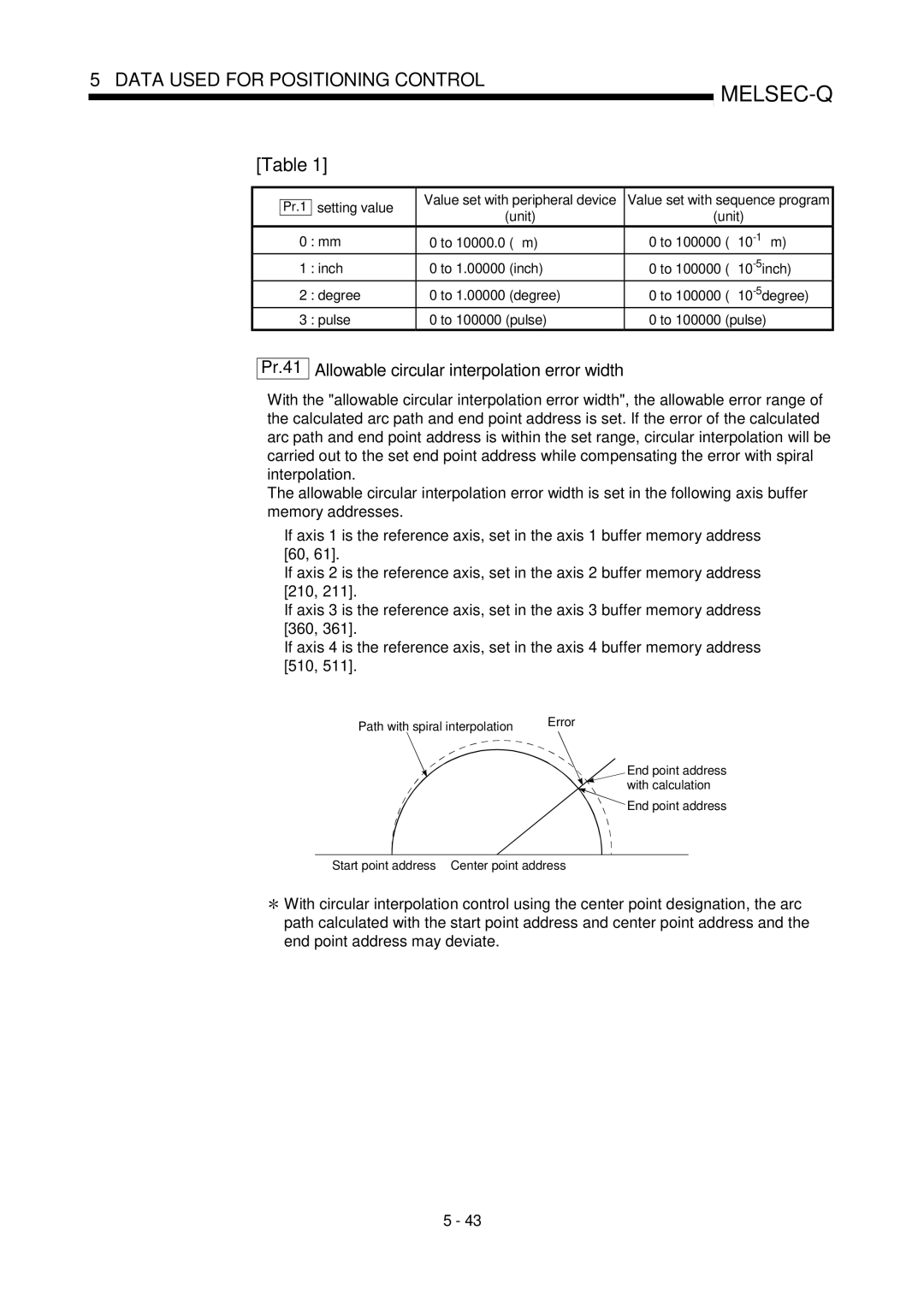
Start point address Center point address
Pr.41 Allowable circular interpolation error width
Path with spiral interpolation Error
With calculation
External command enable
Pr.42 External command function selection
To enable the external command signal, set the to
Memo
Pr.43 OPR method
OPR basic parameters
Pr.46 OPR speed Pr.47 Creep speed
Positive direction address
Degree To 359.99999 degree To 35999999 ⋅ 10-5degree Pulse
Pr.1 Setting value
Pr.44 OPR direction
Pr.44
Pr.46 OPR speed
Pr.45 OP address
Pulse To 1000000 pulse/s
Pr.47 Creep speed
Set a speed equal to or faster than the bias speed at start
OPR speed Pr.47 Creep speed Pr.7 Bias speed at start
Pr.48 OPR retry
Memo
OPR dwell time value
When stopper method 1 is set for
OPR detailed parameters
Pr.49 OPR dwell time
Acceleration time
Pr.51 OPR acceleration time selection
Pr.52 OPR deceleration time selection
Use the value set
Pr.53 OP shift amount
Pr.57 Dwell time during OPR retry
Pr.55 Deviation counter clear signal output time
Pr.54 OPR torque limit value
Pr.56 Speed designation during OP shift
List of positioning data
Before explaining the positioning data setting items
599 600
2-axis interpolation only
Operation pattern
Axis to be interpolated
Da.3 Acceleration time No
Da.1 Operation pattern
Da.2 Control system
Da.6 Positioning address/movement amount
Absolute ABS system, current value changing
Da.4 Deceleration time No
Da.5 Axis to be interpolated
Da.2
Position-speed switching control
Speed-position switching control
Da.2 Setting value
When Pr.1 Unit Setting is pulse
When Pr.1 Unit Setting is inch
Memo
End point address Address set with Da.6
Da.7 Arc address
Da.7 Arc
When Pr.1 Unit Setting is mm
Da.8 Command speed
Value set with peripheral Value set with sequence Da.2
Setting value Setting item
Da.2
Repetition count
Da.1
Da.9 Dwell time/JUMP designation positioning data No
Memo
Start block
List of block start data
Block
Da.11 Da.14
Pages that follow explain the block start data setting items
7001 Axis
Settings Axis
Block Axis
7000 Axis
26000 27000 28000 29000 Shape Positioning data No
Device End
Shape
Continue
Da.13 Special start instruction
How to start the positioning data set Start data No
Da.11 Shape
Da.12 Start data No
Special start instruction
Special start instruction Setting value Setting details
Da.14 Parameter
Set the value as required for
Block
List of condition data
Da.15 Da.19
Pages that follow explain the condition data setting items
Data Used for Positioning Control Remark
03H Condition operator
Parameter Setting value Default
Condition target Identifier
Operator
Da.17 Address
Da.15 Condition target
Da.16 Condition operator
Condition operator
Da.18 Parameter
Da.19 Parameter
Set the parameters as required for
List of monitor data 5.6.1 System monitor data
When not in test mode
When in test mode
1200
Reading the monitor value Default value
Not in test mode Test mode
Monitoring is carried out with a decimal
Start Minute Second
Storage item Storage details
History Up to 16 records can be stored
Start Hour
Storage buffer memory address common to axes 1 to
0000H
0000
Starting history Up to
Can be stored
Storage details Reading the monitor value
Judgment
1292
Occurrence Axis error was detected
Error Encountered an error
Stores an axis error No
Axis error Stores the time at which an
0000
1357
Encountered a warning
Accesses to flash When the number of write
Error reset operation is
Axis in which
1422 1424 1425
Axis monitor data
0000 H
Axis 1 Axis 2 Axis 3 Axis
Monitoring is carried out with a hexadecimal
800 900 1000 1100
Set by the positioning data used one step earlier
Command speed set by the current positioning data
Axis warning No When
Stores 0 under the speed control
810 910 1010 811 911 1011
Default
807 907 1007 1107 808 908 1008 1108 809 909 1009 1109
Speed-position switching
814 914 1014 1114
0000H 816 916 1016
Monitoring is carried out with a hexadecimal
812 912 1012 1112 0000H 813 913 1013 1113
At other times Stores
For a positioning operation Target value
Address/movement amount
818 918 1018 819 919 1019
Default Storage buffer Memory address Value
0000 H 817 917 1017
Movement amount after
Is stored Is stored when machine OPR starts
Torque limit setting value is stored
Machine OPR completion is stored
300 826 926 1026
Speed limit value due to a speed change or Pr.8
Speed limit flag
Speed change processing
Flag
830 930 1030 1130
827 927 1027 1127
828 928 1028 1128
829 929 1029 1129
Md.48 Deceleration start flag
Positioning data No. being
Last executed positioning
Executed last time
837 937 1037 1137
832 932 1032 1132
0000 H 833 933 1033
835 935 1035 1135
Block start data No to
List of control data 5.7.1 System control data
Buffer memory to the flash ROM
Positioning data No to No
Setting Value
Setting value K
Axis control data
Setting item Setting details Set the positioning start No
Restart command Stopped, set 1
Code OFF request M code on signal turns OFF
Setting
Setting K value
+2147483647
Item to specify a new feed value
Inch Degree
2147483648
Conversion into an integer value
10 n
1505 1605 1705 1805
1506 1507 1606 1607 1706 1707 1806 1807
Speed change Enable/disable selection
Setting item Setting details
New acceleration time value Setting range unit
Setting range unit To 8388608 ms
1512 1612 1712
Set with a decimal 1508 1608 1708 1808 1509 1609 1709 1809
1510 1610 1710 1810 1511 1611 1711 1811 Set with a decimal
Inch Degree Pulse
Setting range
1516 1616 1716
100 1513 1613 1713
1514 1614 1714 1814
1515 1615 1715 1815
⋅ 10-1µm ⋅ 10-5inch
1520 1620 1720
1517 1617 1717
1518 1618 1718 1818
1519 1619 1719 1819
Set a value within the allowable range
Torque limit setting value
Specify a new torque limit stored value
1525 1625 1725
1521 1621 1721 1821
1522 1622 1722 1822 1523 1623 1723 1823
1524 1624 1724
Inch Degree Pulse Pr.1 ⋅ 10-1µm
Speed-position switching control INC mode
2147483647
For that, use this data item to specify a new speed
1530 1630 1730 1830
1526 1626 1726 1826
1527 1627 1727 1827
1528 1628 1728 1828
New speed
Position-speed switching
Target position change value
New address
1536 1636 1736 1836
1532 1632 1732
1534 1634 1734 1834
1535 1635 1735 1835
Stepping should be performed
1544 1644 1744 1844
1540 1640 1740 1840 Set with a decimal
1541 1641 1741 1841
1542 1642 1742 1842 1543 1643 1743 1843 Set with a decimal
Cd.39 Teaching positioning data No
When degree is selected as the unit
1549 1649 1749 1849
1546 1646 1746
1547 1647 1747 1847
1548 1648 1748 1848
Memo
Sequence Program Used for Positioning Control
Process during overrun
Precautions for creating program
Reading/writing the data
Restrictions to speed change execution interval
Program, the unit of 0 mm is set for the basic parameter
System configuration
Control unit
Communication with QD75
X0C
List of devices used
Command Time change X35
Code OFF command Commanding M code OFF
Forward run JOG/inching command
Reverse run JOG/inching command
Storage
Enable command Operation enable
M10 Manual pulse generator operation
Requesting acceleration/deceleration
Data resisters and timers
Enable
Acceleration time setting Low-order 16 bits
Acceleration time setting Value High-order 16 bits
Deceleration time setting Low-order 16 bits
Rotation Unit magnification
Pulse output mode
Pulse output mode Rotation direction setting
Command speed
Creating a program
General configuration of program
Positioning control operation program
Refer to Section
From previous
Positioning program examples
MELSEC-Q
Setting of special start instruction to normal start
Position-speed switching operation positioning data No
No M code OFF program Not required when M code is not used
No Manual pulse generator operation program
No Torque change program
ABS data setting and ABRST1 instruction execution
No Flash ROM write program
This program forcibly turns OFF the OPR request flag
External command function valid setting program
Data requiring setting
Time chart for OPR OFF request
Positioning start point No
Start details setting program
Procedures for setting the starting details
Cd.25
Position-speed switching control speed change
Used to set a new value when speed is changed
To validate position-speed switching signal, this
Buffer memory 1500
Start program
Starting conditions
Operation when starting
Starting by inputting positioning start signal
9001
Starting time chart
X10 OFF
X8 OFF 9002
Time chart for starting fast OPR
Time chart for starting major positioning control
Time chart for starting position-speed switching control
Machine OPR operation timing and process time
Follows
Position control operation timing and process time
Restrictions
Starting by inputting external command signal
Setting details Buffer memory address Value Axis
Set to 1 Validate external command 1505 1605 1705
Cd.18
Continuous operation interrupt program
Operation during continuous operation interruption
Restrictions
Set the following data to interrupt continuous operation
Control data requiring settings
Cd.3
Stop with stop command
Restart program
Restart operation
Set the following data to execute restart
Control data requiring setting
Axis operation status is 1 Stopped Signal state
Starting conditions
14 Time chart for restarting
Time chart for restarting
Stop process
Stop program
Pr.36
Types of stop processes
Pr.30 Pr.10 Pr.28 Pr.29
Sudden Stop cause Sudden stop deceleration process
Order of priority for stop process
Memory Configuration and Data Process
Area configuration Memory
QD75 is configured of the following two memories
Details of areas
QD75
Data is backed up User accesses Here
Buffer memory area configuration
Data transmission process
From command To command
Power supply ON/memo area PLC CPU reset
PLC Ready signal Y0 OFF on
Pr.1 Pr.7 Pr.11 Pr.24 Pr.43 Pr.57 Pr.150
Transmitting data with to command from PLC CPU
Accessing with from command from PLC CPU
Pr.8 Pr.10 Pr.25 Pr.42
Memo area Flash ROM write Flash ROM request Write
Flash ROM request Write
Cd.1
Flash ROM write
Flash ROM request writing
QD75 read, monitor
Writing data from peripheral device to buffer memory
Reading data from buffer memory to peripheral device
Completion
Ex. Setting the positioning data
Following methods can be used to set the positioning data
12- 1 to 12
11- 1 to 11
Memo
OPR Control
Outline of OPR control 8.1.1 Two types of OPR control
Restricted, Combination not possible
When an OPR is not required
OPR sub functions
OPR from peripheral devices
Pr.45
Machine OPR Outline of the machine OPR operation Important
Machine OPR operation
OP address is a fixed value set by the user
Machine OPR method
Pr.51
Operation chart
OPR method 1 Near-point dog method
Machine OPR is started
Pr.48
Precautions during operation
Pr.55
OPR method 2 Stopper method
Pr.44 Pr.46
Pr.49
Set a value
OPR speed, thus causing an error
Always limit the servomotor torque after
Md.31 Status b4
Torque limit Near-point dog OFF Machine OPR start
Pr OPR speed Pr Creep speed Stops at stopper Zero signal
OPR method 3 Stopper method
Status b3 OPR complete flag
Zero signal Near-point dog OFF Machine OPR start
OPR speed Pr Creep speed
Md.31 Status b4 Deviation counter clear output
Pr.47 Pr.44
OPR method 4 Stopper method
Machine moves at
OPR direction. Torque
Standing by OP address
OPR direction. It then moves at
OPR method 5 Count method1
Pr.46
OPR speed to
Pr.50
Direction designated
OPR method 6 Count method
Machine OPR is started
Pr.44 OPR direction. It then moves at Pr.46 OPR speed when
Setting for the movement amount after near- point dog on
Fast OPR operation
Fast OPR Outline of the fast OPR operation
Operating restrictions
Operation timing and processing time of fast OPR
Memo
Control unit degree handling
Major Positioning Control
Outline of major positioning controls
Reverse run Position control Position/speed
Speed-position switching control Speed/position
Nonexecutable control system. When this instruction is
Reverse run
Major positioning control from peripheral devices
Data required for major positioning control
Major positioning control sub functions
Operation patterns of major positioning controls
XC, XD, XE, XF
Independent positioning control Positioning complete
X14, X15, X16 Dwell time Time
Start complete signal X10, X11, X12, X13 OFF
Continuous positioning control
Pr.19
Continuous path control
Deceleration stop conditions during continuous path control
Interpola Tion axis
Forward run command Reverse run command
Speed 3000 2000 1000
Speed handling
X14, X15, X16, X17 OFF
Speed switching Refer to Pr.19 Speed switching mode
X14, X15, X16
Start complete signal X10, X11, X12, X13 OFF Busy signal
MELSEC-Q
Incremental system
Designating the positioning address
Absolute system
Value is changed to a new value
Confirming the current value
Values showing the current value
Md.21 Machine feed value
Axis Md.20 Current feed value
Monitoring the current value
Da.6
Buffer memory addresses
Control unit degree handling
Software stroke limit valid/invalid setting
Setting to validate software stroke limit
Setting to invalidate software stroke limit
Moved from 315 to Moved from 45 to
Using
Cd.40
Incremental system
When the software stroke limit is valid
Control, 4-axis speed control Axis
Interpolation control
Meaning of interpolation control
Axis linear interpolation control, 4-axis fixed-feed
Positioning address Forward run speed 2, 3, Movement amount
Setting the positioning data during interpolation control
Deceleration time No Data
Axis to be Interpolated
Pr.20
Starting the interpolation control
Interpolation control continuous positioning
Speed during interpolation control
Interpolation will be stored
Limits to interpolation control
Axis operation status during interpolation control
Speed limit
Speed Position
Interpolation Axis, 4-axis Switching
Positioning data setting items
Position control Speed control
No. at Jump
Arc address Command speed
Jump instruction
Da.9 Dwell time
1-axis linear control
Positioning data setting example
2 1-axis linear control
Axis linear control ABS linear
Axis linear control INC linear
Positioning address/movement amount
3 2-axis linear interpolation control
Axis linear interpolation control ABS linear
2-axis linear interpolation control
Set absolute system 2-axis linear interpolation control
Axis Setting item Reference Axis setting Example
Signal Da.10 Code
Data will not be executed Da.2 Control system
Start point address Axis Current stop position
Axis linear interpolation control INC linear
Positioning address
Da.8 Command speed
Set this when other sub operation commands are issued
Da.6 movement amount
Forward direction Axis
4 3-axis linear interpolation control
3-axis linear interpolation control
At deceleration
Setting not required setting value will be
Output of the positioning complete signal
Positioning data will not be executed
Major Positioning Control Points
6000
Movement amount Reverse direction
Start point address X1, Y1, Z1
Stop address after the positioning control Axis 5000
Deceleration time Pr.10 Da.4
Set incremental system 3-axis linear
Major Positioning Control Points
5 4-axis linear interpolation control
Operation pattern Positioning
Axis Arc address Command speed
Code Setting details
Pr.1 Unit setting
Axis linear interpolation control INC linear
500ms Da.10
Setting not required setting value will be ignored
1-axis fixed-feed control
6 1-axis fixed-feed control
Set 1-axis fixed-feed control Da.3 Acceleration time
2-axis fixed-feed control
7 2-axis fixed-feed control interpolation
Set the time the machine dwells after the positioning stop
Speed may exceed
Set 2-axis fixed-feed control
Pr.20 Interpolation Mm/min Speed designation method
3-axis fixed-feed control
8 3-axis fixed-feed control interpolation
Designated movement amount
Restrictions
5000.0 6000.0
Set 3-axis fixed-feed control
4-axis fixed-feed control
9 4-axis fixed-feed control interpolation
Interpolated Da.6
Movement amount Axis Da.7 Arc address Da.8 Command speed
Axis side speed may exceed
2-axis circular interpolation control
Unit setting When the units set
Sub point designation
If the self-axis is set, an error will occur
3000.0 ∝ Pr.1 Setting is set to mm
Set the speed when moving to the end point address
Movement amount
Restrictions
Speed Pr.20 Interpolation speed designation
Pr.1 Unit Setting is set to mm
With sub point designation
Pr.25 Acceleration time 1 as Acceleration time at start
Counterclockwise
Can be controlled
Clockwise
Pr.41
Circular interpolation error compensation
Positioning address/movement Refer to
Arc address Reverse direction
Arc address
Forward direction
Radius Reverse direction
Restrictions
Counterclockwise according to the control
Positioning data setting examples
Axis Arc address Command speed Da.9 Dwell time Da.10 M code
Center point designation. Select clockwise or
Movement amount =
Restrictions
8000.0 ∝
Unit setting is set to mm
With center point designation. Select clockwise or
INC circular
12 1-axis speed control
Pr.18
Current feed value during 1-axis speed control
Set Positioning complete
Control Da.2 Control system
Axis 1 Positioning data No Setting item
Da.10 Code Code on signal output
Timing setting only possible in the with mode
Md.31 Status b0
13 2-axis speed control
Current feed value during 2-axis speed control
Command speed Examples
Setting item Pr.8 Speed limit value
Set 2-axis speed control
Axis Da.8 Command speed Da.9 Dwell time
Mm/min Setting not required setting value will be ignored
11 3-axis speed control operation timing
14 3-axis speed control
Restrictions Set Positioning complete
Current feed value during 3-axis speed control
8000.00mm/min 6000.00mm/min 4000.00mm/min Speed
Axis 1 setting Axis 2 setting Axis 3 setting
4000.00mm/min 5000.00mm/min 6000.00mm/min Value Command
Speed limit
Output timing setting only possible
Da.8 Command speed Da.9 Dwell time Da.10 M code Axis
Setting other than Positioning complete is
Set the speed to be commanded
4-axis speed control
15 4-axis speed control
12 4-axis speed control operation timing
Current feed value during 4-axis speed control
Speed Min
Axis Setting item
Setting Speed limit 4000.00mm 5000.00mm 6000.00mm 8000.00mm
Value Min Command 8000.00mm 6000.00mm 4000.00mm 1500.00mm
Setting only possible
Setting other than Positioning
Set this when other sub
Code on signal output timing
Setting item Setting details Buffer memory address Value
Speed-position switching control INC mode
Switching over from speed control to position control
Speed-position switching control INC mode
Md Status b0
MELSEC-Q
Follows parameters
Current feed value
Switching time from speed control to position control
Md.20 Current feed value Speed control setting
Following table shows
Cd.23
Speed-position switching signal setting
Changing the position control movement amount
Pr.21 value
Status b1 of the axis monitor area
Acceleration time No Pr.25
Position switching control INC mode
Set speed-position switching control by forward run
Speed/position
Unit setting
Speed-position switching control ABS mode
X14,X15,X16,X17
Cd Speed-position Switching enable flag Speed control flag
Unit setting of 2 degree
Pulse
Current feed value
Speed control setting is other than
Pr.21 Md.20
Speed-position switching signal setting
Speed-position switching signal Added
Axis Movement amount Arc address
Position switching control ABS mode
Switching over from position control to speed control
18 Position-speed switching control operation timing
External position-speed switching signal
Position control carried out until position-speed switching
Signal turns on
Status b5 turns on
Current feed value during position-speed switching control
Switching time from position control to speed control
Current feed value during speed
V2 becomes the speed control command speed
Position-speed switching signal setting
Changing the speed control command speed
Speed limit value if a new speed exceeds
Status b5 of the axis monitor area
Da.1 Positioning
Set position-speed switching control
Unit setting is
Setting value will be ignored
Md.21
Changing to a new current value using the positioning data
Current value changing
Current feed value is changed to the value set
Command Setting not required Setting value is Speed Ignored
Axis to be Setting not required Setting value is
Setting is set to mm
Arc address Setting not required Setting value is Ignored
Cd.9
Current value changing procedure
Current value changing, setting 9003
Following shows a start time chart
Setting method for the current value changing function
PLC CPU
Operation
NOP instruction
Jump instruction
Simultaneous start condition data cannot be set
Set the Jump instruction
Code Unconditional Jump Condition data No
Acceleration time No
Set the Loop
Loop
Loop to Lend loop is repeated by set repeat cycles
Set the Lend
Lend
Ignore the Lend before the Loop is executed
10.3.5
10.3.2
10.3.3
10.3.4
High-level positioning control from peripheral devices
Outline of high-level positioning control
High-level positioning control sub functions
Designate
Data required for high-level positioning control
Start data set in the next point
Special start Da.12 Da.13
Block start data and condition data configuration
7001 7004
Positioning start No. in Step
High-level positioning control execution procedure
Da.14 Parameter
Condition Next start Da.11 End
Da.12 Start data No Da.13
No.
Block start normal start
Setting examples Block start data setting example
Positioning data setting example
Block start control example
Control examples
Parameter is carried out for the positioning data set
Condition start
Axis 1 block Da.11 Da.12 Da.14
Wait start
3rd point End
Simultaneous start
A simultaneous start, the positioning data set
Da.13 Axis 1 block Da.11 Da.12 Da.14
Condition data Nos. have been set Da.14
Repeated start for loop
Parameter of the block start data in which For loop is set
Repeated start for condition
8th point
Restrictions when using the Next start
6th point
7th point
Repeated start
Condition data is set in the following cases
Control type High-level positioning control
Wait
Words 05H P1≤
Memory P1 numeric value Set only when Da.16 Address
03H Buffer memory 01H =P1 Word 02H
04H Buffer memory
QD75 buffer memory Address 30000 30099
Condition Device X0 =QD75 Ready is OFF
Condition data setting examples
Setting the device ON/OFF as a condition
Following shows setting examples for condition data
Control details
Multiple axes simultaneous start control procedure
Multiple axes simultaneous start control
Setting examples
Points
1501
Input/output signal Y10
QD75 Buffer memory Drive unit
7000 1500
Start conditions
Control data that require setting
Start time chart
Start time chart
Positioning data setting example
To H0 K1500 K7000
Creating the program
Example Set the block start data beforehand
M104 Y10 X10
11.2.5
Manual Control
Inching operation
JOG operation
Monitoring manual control
Manual pulse generator operation
Manual control sub functions
Carrying out manual control from peripheral devices
JOG operation
JOG operation Outline of JOG operation Important
Cd.16
Errors during operation
Cd.17
JOG operation timing and processing times
JOG operation timing and processing time
JOG operation is carried out by the following procedure
JOG operation execution procedure
Setting the required parameters for JOG operation
Deceleration time 1 Unit pulse
Acceleration time 1 Unit pulse 1000
Acceleration time 2 Unit pulse
Acceleration time 3 Unit pulse
JOG speed is set to 100.00mm/min in the example shown
Required control data setting
Creating start programs for JOG operation
JOG operation start time chart
Creating the program
JOG operation example
When the stop signal is turned on during JOG operation
Y9, YB, YD, YF
Busy signalXC, XD, XE, XF OFF
Forward run JOG operation Forward run JOG start
Signal Y8, YA, YC, YE
Forward run JOG operation execution Test mode
Forward run JOG start signal OFF Y8, YA, YC, YE
Y4, Y5, Y6, Y7 100ms Rise of JOG start signal is ignored
Forward run JOG operation Forward run JOG start signal
Inching operation
Inching operation Outline of inching operation Important
Limit signal
Depending on
Inching operation timing and processing times
Inching operation is carried out by the following procedure
Inching operation execution procedure
Pulse output to the drive
Setting the required parameters for inching operation
Setting item Setting requirement Factory-set initial value
Pr.1 Pr.2
Inching
Creating a program to enable/disable the inching operation
14 Inching operation start time chart
Creating the program
Inching operation example
When stop signal is turned on during inching operation
16 Operation when JOG start signal is turned on in test mode
Cd.21
X10, X11, X12 Manual pulse generator operation enabled
Manual pulse generator operation
Create the sequence program so that
Operation possible Operation not possible Upper/lower
Restricted items
64 to 28.4 to 57.6
Manual pulse generator operation timing and processing time
For example, when
Position control by manual pulse generator operation
Speed control by manual pulse generation operation
Manual pulse generator operation execution procedure
Manual pulse generator input selection
Torque limit setting value Unit % 300
Input signal logic selection
Cd.20 Generator 1 pulse Magnification
Generator operation when finished with
Manual pulse Set the manual pulse generator 1 pulse input
Start complete signal X10 OFF Busy signal
Forward run Reverse run Pulse input Phase PLC Ready signal
No.13 Manual pulse generator operation program
Memo
12.3.1
12.1.1
12.2.1
12.2.2
It cannot be invalidated with parameters
Outline of sub functions
Following table shows the types of sub functions available
Timing known
Trigger for the sub work
Direction opposite to the Pr.44 OPR direction
Sub functions specifically for machine OPR
OPR retry function
Movement starts
OPR direction is set to 0 Positive
OPR direction, a
Pr OPR direction Stop by limit Machine OPR
Setting the dwell time during an OPR retry
Dwell time during OPR retry
Precaution during control
Setting the OPR retry function
Setting item Setting details Factory-set Value
OP shift operation
OP shift function
OPR speed or
Setting range for the OP shift amount
Movement speed during OP shift
Status b4
Precautions during control
Setting the OP shift function
Backlash compensation function
Functions for compensating the control
255
Setting the backlash compensation function
Current feed value or
Backlash compensation, which includes the movement amount
Pr.2
Electronic gear function
Definition
Error compensation method
Procedure
No. of pulses per rotation Ap
Set the post-compensation
Actual speed
Relation between the movement amount per pulse and speed
Remark
Positioning data No Positioning data No
Near pass function
Da Positioning address Path of positioning data No.3
Axis 2 output speed
Axis 1 output speed
Example Near pass
Allowable circular interpolation error width
Speed limit function
Functions to limit the control
JOG speed JOG speed limit
Setting the speed limit function
If any axis exceeds
200000
New torque value is set to
Torque limit function
Pr.17
When limiting the torque at
Torque limit setting value, confirm That
Torque limit stored value
Setting the torque limit function
Software stroke limit lower limit
Software stroke limit function
Pr.13
Workpiece moveable range
Md Current feed value Md Machine feed value
When machine feed value is set
Current feed value and range limit check
Pr.14
Software stroke limit check details
No.10 P11 No.11 No.12 No.13 No.14 P01
Precautions during software stroke limit check
Software stroke limit upper Limit value
Pr.12
Software stroke
Setting the software stroke limit function
Invalidating the software stroke limit
For manual operation, set 0 software stroke limit invalid
315º
Setting when the control unit is degree
Setting the software stroke limit
Current value address
19 Hardware stroke limit function operation
Hardware stroke limit function
Input signal logic selection is the initial value
Wiring the hardware stroke limit
When the hardware stroke limit function is not used
Input signal logic selection is set to the initial value
Speed changes to Operation during
Functions to change the control details
Speed change function
Following drawing shows the operation during a speed change
Or later
Function version Restarting speed Da.8 Command speed
Cd.14
Positioning operation Speed change 0 flag
Status b10, and enable
Speed limit value when the value set
New speed value is equal to or larger than
Speed change Cd.15 Set 1 Change the speed
Setting the speed change function from the PLC CPU
Following shows the speed change time chart
Cd.14 New speed value 2000 Set the new speed
No.14 Speed change program
Cd.14 New speed value
Cd.8 Set 1 Validate the external command
Pr.42 Set 1 External speed change request
Valid
K62
Input the external command signal
Write 1000000 to D108 and D109
K1514 D108
Md.22
Override function
Feedrate becomes a value of 1 or less. When
Cd.13
Positioning Cd.13 Operation speed
Setting the override function
MELSEC-Q
Cd.10 Cd.11
For an acceleration/deceleration time change enable setting
Acceleration/deceleration time change function
Pr.9 Pr.10 Pr.25 Pr.30
When 0 is set in Cd.10 New acceleration time value
New deceleration
Setting the acceleration/deceleration time change function
New acceleration
Cd.10 Set the new acceleration time Time value
No.16 Acceleration/deceleration time change program
Example
31 Torque change operation
Torque change function
If a value besides 0 is set
Setting the torque change function start signal
QD75 Operation Panel Module
Absolute position restoration function
Servomotor with absolute position detector PLC system
PLC system Pulse train Servo amplifier
QD75 Command
Battery Servomotor Pulse/rev cumulative rotation
Outline of absolute position detection data communication
Instruction
Absolute position signal transmission procedure
Dedicated
Transmission mode
Signal name Abbreviation Pin No Function and application
ABS transmission mode terminal. While this is turned on
This is turned on when ABS data is requested in the ABS
Unit ∝ m
Controlling instructions
Condition 1. Number of output pulses
Condition 2. Positioning address
Detection system
Concept for the unit of mm, inch or pulse
Example
26843545.6 26843545.5 Unusable range Absolute position
Usable range in absolute
Concept for the unit of degree
Step operation not possible
Other functions
Step function
Relation between the step function and various controls
Step start information
Step mode
Deceleration unit step
Data No. unit step
Turn OFF the step valid flag, and quit the step function
Using the step operation
Set the step mode before starting the positioning data
Write 1 restart to
Positioning start signal RYn+10, RYn+11
Cd Step valid flag Positioning start signal
Y10, Y11, Y12, Y13 Busy signal
XC, XD, XE, XF Positioning complete signal
Cd.35 Step valid flag Set 1 Carry out step operation
Step function settings
Set 0 Deceleration unit step or 1 Data No Cd.34 Step mode
Unit step
Following drawing shows the skip function operation
Y10, Y11, Y12, Y13 BUSYsignal
Skip function
Setting the skip function from the PLC CPU
K62 K3
Setting the skip function using an external command signal
Cd.8 Set 1 Validate external command
Pr.42 Set 3 Skip request
Md.25
Code on signal output timing
With mode
Code output function
Code OFF request
After mode
Point
Pr.18
Setting the M code output function
Reading M codes
M code No Code set
Addresses for which teaching is possible
Teaching function
Control details Teaching timing
Designates the data to be taught Teaching
Data used in teaching
Following control data is used in teaching
Selection Written to Arc address
YES
Teaching procedure
MELSEC-Q
Motion path
Example Target position
Setting conditions
Teaching program example
Program example
Point
Details of control
When the direction of the operation is changed
Target position change function
Precautions during operation
Set 1 Carry out speed change
Following shows the time chart for target position change
No.22 Target position change program
Command in-position function
Width check
Command in-position width and command in-position flag
Execution of the command in-position
Pr.16
Remaining distance to the stop position of the position
Setting the command in-position function
Confirming the command in-position flag
Command Turn on the command in-position flag, and set Pr.16
Acceleration/deceleration processing function
Velocity
Pattern acceleration/deceleration processing method
Speed change request Speed change deceleration
Set the acceleration/deceleration curve when 1 is set
Pattern acceleration/deceleration processing
Controls
Pre-reading start function
Cutter Cutter shaft Feed shaft Stock
49 System example using pre-reading start function
Feed shaft Start
Program examples
MELSEC-Q
Start made with positioning data No. specified
Deceleration start flag function
Start data No
Block start Da.11 Da.12
Data Shape
Precautions during control
Set whether the deceleration start flag function
Deceleration start flag function setting method
Checking of deceleration start flag
Monitor item Storage details
Control
Stop command processing for deceleration stop function
Deceleration curve re-processing
Deceleration curve continuation
Precautions for control
Setting method
Common Functions
Outline of common functions
Parameter initialization means
Parameter initialization function
Initialization request
Parameter initialization method
Parameter
Parameter Cd.2 Set 1 parameter initialization request 1901
Md.19
Execution data backup function
Execution data backup written to flash ROM means
Flash
Execution data backup method
Shown in the following table
External I/O signal logic switching function
Parameter setting details
Precautions on parameter setting
External I/O signal monitor function
14.6
14.3
14.4
14.5
Interlock during dedicated instruction is executed
List of dedicated instructions
Setting data
Functions
Control data
Abrst instruction Execution completion
Output
Points
Processing processing
Precautions
Errors
Program examples
Dedicated Instructions PSTRT1, PSTRT2, PSTRT3, PSTRT4
9000 to
Machine OPR 9001
Fast OPR 9002 Current value changing 9003
7000 to User
Complete state display OFF
Sequence program
Pstrt instruction Execution completion
Program examples
Dedicated Instructions TEACH1, TEACH2, TEACH3, TEACH4
Positioning data No. for which teaching is carried out User
Teaching data Current feed value is written is set
Current feed value is written to positioning address
Teach instruction Execution completion
Program example
Other than
Device Setting data Setting side
Pfwrt
Pfwrt instruction Execution completion
Instruction symbol
Sequence program Processing
Precautions
Program example
Pinit
Device Setting data Setting range Setting side
Instruction symbol Execution condition
Other than 0 Abnormal completion error code
Pinit instruction Execution completion
Initialized setting data Parameters
Positioning data No to No Block start data No to
Program example
15.4
15.3
Types of errors
Error and warning details Errors
Types of warnings
Error storage
Axis error No
Status for axis status storage
Resetting errors and warnings
Confirming the error and warning definitions
Invalid operations
Memo
List of errors
OFF. Turn OFF the on commands
After making an axis error reset refer to 3 in Section
Check whether the stop commands output
Signals/external inputs to QD75 are turned on or
OPR speed by the stopper method Count method 1
Near-point dog signal is turned
Dwell time fault
OP detection timing Detailed parameter 2 Sudden stop
Bring the JOG speed into the setting range
Lower the OPR speed Increase the dog signal input time
Adjust the near-point dog position so that
Review the wiring. Refer to Section
Current speed is set for speed
Position switching control
When multiple axes are started
To 600, 7000 to 7004, and 9001 to 9004
Axis 1 start data No 1640 1740 1840
Refer to .5 Da.16
60H, 70H, 80H, 90H, A0H
B0H, C0H, D0H, E0H
At start The system will not operate
Where the control unit is set to
Operation status at error occurrence
Correct the circular interpolation error allowable limit
Setting with sequence program
When software stroke limits are Valid
2147483648 to When software stroke limits are Invalid
Operation pattern sets a new Not possible
Control falls outside
Value range
Control unit is set to degree Control system sets an
At start Bring the current feed value into the software
Stroke limit using the manual control
Position switching control, and position-speed
1506 1606 1706 1806
Sudden stop selection Axis not present Stop group
Axis linear interpolation control Error
Interpolation axis Operation of the interpolation axis
Unit group Units are different at the parameter
To 2000000000 mm/min or others Refer to .3 Da.8
Correct the positioning data or change the parameter
Are in line with each other
Sub point setting End point = sub point Error
Prohibited area Either of the following applies
Designated Start point = sub point
Correct the positioning address. Refer to .2.16, 9.2.17
Axis Same as error codes 515 to
Correct the control system or parameter. Refer to .1.6
Positioning start is carried out 537
536 When an M code on signal X4 to Start
X7 is turned on
Refer to .4 Da.13
After turning OFF the M code on signal, start
Signal. Then start the system
Correct the instruction code of the special start data
Error Executed with the teaching data Stop selection
Direction in unit Set outside the setting range
Hold error Output at error stop, the setting for
Setting deceleration 9001 to Stop/sudden stop
Output at error stop
Set the ABS setting direction in the unit of degree
Within the setting range
Set 0 when the software stroke limits are valid
Outside the setting range Range
Outside unit setting
Range Outside the setting range Outside unit
Error Setting range Rotation direction
Set the bias speed to not more than the speed limit
PLC Ready signal Y0 from OFF to on
Set the value converted into the pulse number using
Bring the setting into the setting range
Speed changeover
Error Error name Operation status at error
Setting value Setting range Code on timing
Mode error
Degree 0 to Value is smaller than the upper limit value
Mm inch pulse Bring the setting into the setting range
Speed-position switching control ABS mode should
Turn the PLC Ready signal Y0 from OFF to on
Circular interpolation Error width
Detailed parameter Setting error
Axis 1 Axis 2 Axis 3 Axis 194 344 494 195 345 495
196 346 496 PLC Ready signal Y0 from OFF to on 197 347 497
Bring the setting into the speed limit value or below
Creep speed error
OPR direction error
Setting range OP address setting Set range of the OPR basic
OPR speed error Setting range Set range of the OPR basic
226 376 526
Axis 1 Axis 2 Axis 3 Axis 221 371 521
Set the speed to the bias speed at start or higher
225 375 525
List of warnings
Deceleration with the JOG start signal OFF
Do not issue the restart command when the axis
Carry out the teaching request when the axis is not
Set a value within the setting range
Command function
When input magnification is set at
Limit value when the speed is
Termination setting
Give a request at the position where there is an
Magnification to within the setting range
With a stop command, during stoppage, or during
Do not turn on the speed-position switching signal
Classification Warning
Outside command Command speed exceeds
Continuous path control is used
Set the teaching data selection set value to within
Following cases
During deceleration stop. An operating pattern
LED display functions
Appendix 8.1 Connection example of QD75D ∑ series
Appendix 4.1 Connection example of QD75D MR-H
Appendix 4.2 Connection example of QD75D MR-J2/J2S- a
Appendix 4.3 Connection example of QD75D MR-C
Additional devices
Function comparison
Additional buffer memory
Memo
MELSEC-Q
MELSEC-Q
Appendix 2.2 Parameter setting value entry table
20000 1000 2147483647 2147483648 300
Initial value Axis Remarks
Interpolation error width
Setting Upper limit External B7, b9 Unused Each bit value
Generator input Positive Command Deviation Unused Logic
Input selection Phase/B phase multiple PULSE/SIGN mode
Initial value Axis Remarks 1000 20000 300
OPR direction
Creep speed Do not retry OPR with upper/lower limit switch
Setting for the movement amount
Deviation counter clear signal To 65535ms
Initial value Axis Remarks 300
Time Ted Movement Amount
Control Accelera
Arc
Dwell Code Pattern System Tion time Interpola Address
2015 2016 2017 2018 2019
2002
2005 2006 2007 2008 2009
2012
Posi Command Positioning Arc data
4022 4024 4025 4026 4027 4028 4029 204
201
4002 4004 4005 4006 4007 4008 4009 202
4012 4014 4015 4016 4017 4018 4019 203
5032 5034 5035 5036 5037 5038 5039 305
5002 5004 5005 5006 5007 5008 5009 302
5012 5014 5015 5016 5017 5018 5019 303
5022 5024 5025 5026 5027 5028 5029 304
6022 6024 6025 6026 6027 6028 6029 404
401
6002 6004 6005 6006 6007 6008 6009 402
6012 6014 6015 6016 6017 6018 6019 403
7032 7034 7035 7036 7037 7038 7039 505
7002 7004 7005 7006 7007 7008 7009 502
7012 7014 7015 7016 7017 7018 7019 503
7022 7024 7025 7026 7027 7028 7029 504
8032 8034 8035 8036 8037 8038 8039
8002 8004 8005 8006 8007 8008 8009
8012 8014 8015 8016 8017 8018 8019
8022 8024 8025 8026 8027 8028 8029
9022 9024 9025 9026 9027 9028 9029 104
101
9002 9004 9005 9006 9007 9008 9009 102
9012 9014 9015 9016 9017 9018 9019 103
MELSEC-Q
MELSEC-Q
MELSEC-Q
MELSEC-Q
MELSEC-Q
MELSEC-Q
MELSEC-Q
MELSEC-Q
MELSEC-Q
MELSEC-Q
MELSEC-Q
MELSEC-Q
MELSEC-Q
MELSEC-Q
MELSEC-Q
MELSEC-Q
MR-H
TE2
QD75D CN1 Pulse F+ Pulse R+ Clear Clear COM
MR-HDP01 Pulser B
DOG
SON Pulser A+
24G
2m max
B19 Generator
+24VIN
No. of control axes No. of positioning data items
Error display
Start, error, warning
Model QD75P1 QD75P2 QD75P4 A1SD71S2
214748364.8 to Controls
Comparisons of performance specifications
Positioning systems
Command pulse output system
Ation time Setting range
Near pass Error display Error LED
History data storage Start, error, warning
Function comparisons
From the speed limit value is out of the maximum command
Start history storage during error
QD75, errors for the software stroke upper limit are
Integrated into error code 508. Error codes 509 to 512 are
Changed functions
Normal Not Ready Ready signal
Is changed to Error occurring Axis operation status
Step operation is restarted with the restart command
Error code comparisons
A1SD75
Not READY/WDT error
Input/output X/Y comparisons
Added Deleted Fatal warning Common
Buffer memory address comparisons
Near pass mode selection for path control 216 366
Positioning complete signal output time 209 359
Allowable circular interpolation error width
QD75 Pr.42 External command function selection
Start history storage during error 623 Pointer number
Test mode flag 450
Error judgment
Start Second 100 ms Errors
753 1422
Items of A1SD75 QD75
Axis warning No
Start positioning data No. setting value
Speed-position switching control positioning
External input/output signal
Special start data instruction parameter setting
Speed-position switching control movement
Clock data setting hour
Clock data setting minute, second
Axis error reset
Code/condition data
1510 1610 1710
New deceleration time value
Acceleration/deceleration time change during
Parameter Start
4350
4600
4850 Data
Data indication No. comparisons
Setting for the movement amount after near-point dog on
Positioning complete signal output time
Allowable circular interpolation error width
Pr.42 Near pass mode selection for path control
Monitor data
OP absolute position
Speed-position switching control positioning amount
Special start data instruction code setting value
Special start data instruction parameter setting value
Control data
Cd.42
Stop command processing for deceleration stop selection
Interrupt request during continuous operation
Called block start data with the QD75 Appendix
Positioning data, block start data, condition data
Output signal comparisons
Input/output signal comparisons
Input signal comparisons
Appendix 10 Melsec Explanation of positioning terms
Pulse input Phase
No.10 Positioning No.11 Code
After mode
Clamp command
No.1 No.2
Female thread Male thread
Auto Tuning Automatic Tuning
Acceleration Deceleration Speed Time
Forward run Backlash
Full speed Speed Bias speed
BIN Binary
C D
Change signal
CCW Counterclockwise
Refer to term Feedback Pulse
No.2 No.4 No.6 No.1 No.5 No.3
CP Control Continuous Path Control
Converter Digital-to-Analog converter
No. of pulses Voltage 0 to ±10V To 80,000 Pulses/second
Receiver
Positioning Drive Motor Module Unit Power supply
Near-point dog of the OPR
Index Scale
Rotary encoder
Linear encoder Appendix
For the main For the zero
Rotation by the motor Lead feedrate per screw rotation
QD75, F is a status where the module itself has a fault
OPR speed Dog switch
Gain
FLS Signal forward limit signal
G50 Max. spindle speed setting
Raising
Right Right No is several millimeters To the right of No
Incremental Encoder
Actuator
Microswitch
KPPS
Y0 Forward run Y1 Reverse run
Made by Mitsubishi Electric Corp. model MR-HDP01
Code Machine Code
Refer to GD2
No.9 Longitudinal Feed No.8 No.1 Latitudinal feed
No. of pulses per Per rotation Encoder rotation
NC Language Numerical Control Language
P rate. Refer to the term P Rate
Rate
This point is the reference
OPR Method
Feedback pulses PG0 1 axis rotation
Pronounced pee-jee-zero. Refer to the term Zero Signal
Rate Pulse Rate
PG0 Pulse Generator Zero
Loop gain
Command pulse frequency
Dwell time Positioning complete signal
Refer to the term Operation Pattern
Type Terminal
PTP Control Point To Point Control
Refer to the section of term operation pattern
Forward Reverse
RLS Signal reverse limit signal
REAL-TIME Auto Tuning Real-time Automatic Tuning
Motor PLG Encoder
SFC Sequential Function Chart
Execution of extrusion
QD75 Ready Servo amplifier
Speed Control
Start Switching signal High speed Incremental positioning
Machine OPR Stopper
Refer to the term Dwell Time Appendix
Motor torque MotorLoad
Positioning possible in a 3m 9.84feet range
Limit switch
Torque width variations, deviations in the torque
Lower limit Upper limit Stop
Base table Axis
Also called PG zero. Refer to Zero Signal
Rotated by the motor
Appendix 11 Positioning control troubleshooting
How can the deceleration stop
8192 Setting of 1 m 1pulse is
Changed 1pulse cannot be achieved Thus, the setting 1 m
Trouble type Questions/Trouble Remedy
Machine OPR, the message
Trouble type Questions/Trouble
Movement amount per No. of pulses per
No. of pulses Rotation
Setting is Deceleration stop, it will be ignored. The same
Signal should be turned on at 4ms or more
If possible, set the signal so it does not turn on only
Selected? Setting value
Set to Is it possible to count the pulses Not possible
When a JOG operation is
How can it be canceled? Changing has been executed
PLC Ready signal Y0 turns on Module
Unit magnification to 10-fold or Is set to
To on Parameters When the start signal was turned
Signal ON, warning 100 start
Is there any problem if
Appendix 12 List of buffer memory addresses
Setting for the movement amount after
1422
Axis in which the error
Error history pointer
Occurrence Hour
Memory area Axis monitor data Monitor data
Md.30 External input/output signal
Special start data instruction No. setting
815 915 1015 1115 Amount
Memory area Axis control data Control data
1515 1615 1715 1815 Speed change request
Axis Simultaneous starting axis start data No
Cd.42 Stop command processing for deceleration
Dwell time/JUMP destination
Buffer memory address Axis Operation pattern
Code/condition data No
No. of Loop to Lend repetitions
50th point
Buffer memory address Axis Memory area Shape
Start data No Point
Data Parameter
PLC CPU memory area
Condition judgement target data of the condition
Unit mm
Appendix 13 External dimension drawing QD75P1/QD75P2/QD75P4
27.4 136
QD75D1/QD75D2/QD75D4
Number
12-63
Axis error occurrence Hour
Axis error occurrence Minute second Md.12 Axis error reset
Command in-position width
Composite speed Explanation of positioning
Details of input signals QD75 PLC CPU
Deviation counter clear signal output time
Appendix-73
External input/output signal
Error correction Explanation of positioning terms
Error reset Explanation of positioning terms
External command function selection
Input signal logic selection
For starting speed-position switching control
For starting with external command signal
Test mode flag
15-36
Limit switch Explanation of positioning terms
Manual pulse generator enable flag
Multi-phase pulse Explanation of positioning
12-18
Multiplying rate setting Explanation of positioning
No. of write accesses to flash ROM
NC language Explanation of positioning terms Appendix-81
Position-speed switching control enable flag
Outline of installation, wiring and maintenance
Output signal logic selection
Position loop mode Explanation of positioning
Positioning starting point No
Precautions
External command function valid setting
Pulse output mode Explanation of positioning
Setting for the movement amount after near-point Dog on
Restart command
RLS signal Explanation of positioning terms
Rotation direction setting
Speed-position switching control Explanation
Special start data instruction code setting value
Special start data instruction parameter setting
Speed-position switching control ABS mode
Time chart for starting position-speed
Stop command processing for deceleration stop
Stop signal Explanation of positioning terms
Time chart
Turntable Explanation of positioning terms
Unit setting Explanation of positioning terms
With mode Explanation of positioning terms
Tracking function Explanation of positioning
Memo
Overseas service
Gratis Warranty Term and Gratis Warranty Range
Gratis Warranty Term
Gratis Warranty Range
Page
Page
QD75-U-S-E 13JR09 SHNA-080058-H0506MEE