Access Navigator
Mailtech-support@carrieraccess.com
Preface
Preface
Compliance
Electrostatic Discharge ESD Precautions
Carrier Access Software License Agreement
License
Title and Risk
Copyright
Warranty
Term
Disclaimer
Jurisdiction and Venue
Limitations of Warranty & Limitation of Remedies
Warranty
Follow Electrostatic Discharge ESD Precautions on
Warranty Product Returns
Table of Contents
Table of Contents
Access Navigator / GR-303 + Data Host
Access Navigator / GR-303 Host with P-Phone
Electrical Installation
Physical Installation
1xv
1xvi August Access Navigator Release
Provision Access Navigator
Provision DCS Service
Start Management Session
Provision Remote Access Bank
Provision GR-303 Service
Provision Remote Adit 600 via IP DS0
Provision Remote Adit 600 via FDL
Diagnostics & Troubleshooting
Alarm Clearing
1xxi
Update Controller Card Software
Maintenance Procedures
CLI Language Reference
1xxiv August Access Navigator Release
1xxv
1xxvi August Access Navigator Release
EOC Interface
Snmp Interface
FDL Interface
Glossary
Index
Chapter
Introduction
Overview
Access Navigator Configurations
Features and Benefits
System Architecture
Access Navigator System Architecture
Carrier Access Support Products
Access Banks
Adit
Management
Command Line Interface
Snmp
Valet and NetworkValet EMS Software
Access Navigator / DCS Service Manager
Access Navigator / DCS Service Manager
Access Navigator / DCS Service Manager
Switch Center Co-location Customer Premises
Functions
Services
Facilities
Management
Network
Quad T1 Framer Card Features Controller Card Features
Configuration
Applications
Specifications
Interfaces
DCS Operation
Alarms
Signaling
System Clocking
Management Interfaces
Compliance
Power
Environmental
Physical
FCC Requirements
Compliance Requirements
Part 15, Class a
Part
Telcordia Bellcore Requirements
Service Order Codes SOC
UL Requirements
Facility Interface Codes FIC
Ordering Information
CSA Requirements
Part Number Description
Access Navigator / GR-303 + Data Host
Access Navigator / GR-303 + Data Host
Access Navigator / GR-303 + Data Host
GR-303 Ethernet RS-232 Modem Voice
GR-303 Services
Lines Management Key System
Access Navigator Data Host Architecture
DCS Services
IP DS0 Management
Management Architecture
FDL Management
Access Navigator FDL Management Architecture
GR-303 call support
Applications
Crossconnects
GR-303 Operation
DCS Signaling
GR-303 Signaling
Compliance
Compliance Requirements
Telcordia Bellcore Requirements
Ordering Information
Access Navigator / GR-303 Host with P-Phone
Access Navigator / GR-303 Host with P-Phone
Access Navigator / GR-303 Host with P-Phone
Access Navigator / GR-303 with P-Phone Architecture
Features and Benefits
Voice Fax
P-Phone Service Support Using Adit 600 Terminals
Phone Services
DCS Services
Management Architecture
FDL Management
Configuration
Applications
Specifications
GR-303 Signaling
Standards
Compliance Requirements
Telcordia Bellcore Requirements
Ordering Information
Ordering Information
Physical Installation
Physical Installation
Compliance and Safety Requirements
Unpacking and Inspection
Tools and Materials
Installation Summary
Precautions Tools and Materials
Horizontal 19-Inch Rack Mount
Attach Access Navigator to Equipment Rack
Attach Mounting Brackets to Access Navigator
Mounting Four per side Bracket Fasten brackets to
Horizontal 23-Inch Rack Mount
Assemble Mounting Brackets
Installation in 23-inch Equipment Rack
Inches minimum
Vertical Rack Mount Using Crossbars
Attach Access Navigator to Crossbars
Install Crossbars
Crossbar Installation
Inch Equipment Rack
Vertical Wall Mount
Precautions
Prepare Plywood
Ensure Adequate Clearance
Attach Access Navigator to Plywood
Wall View
Wire Tie Plywood Sheet Inches Minimum
12. Mounting Hole Pattern on Plywood
13. Wall Mount Bracket Installation
Physical Installation
Electrical Installation
Electrical Installation
Static-Sensitive Equipment Handling Procedures
Tools and Materials Required
Chassis Ground Connection
Connect Ground Wire to Ground Lug
Run Ground Wire to Access Navigator
Attach Ground Lug to Access Navigator
DSX-1 Cable Connections
Prepare DSX-1 Cables
CAC
Location of Rear Panel DS1 Connectors
Connect DSX-1 Cables to Access Navigator
Electrical Installation
Attaching Ferrite Bead RF Suppressors
Attach Ferrite Beads
Connect DSX-1 Cables to Interface or Patch Panel
Card Group
DSX-1 Cable Pin Connections and Flying Wire Colors
Electrical Installation
Information, Tools, and Materials
RS-232 Management Connection
RS-232 DTE-to-DCE Cable
RS-232 DCE-to-DCE Modem Cable Connections
Connect Shielded RS-232 Cable
10. Attaching Ferrite Bead RF Suppressor
Attach Ferrite Bead RF Suppressor
Preconfigure Optional Modem
Ethernet Management Connection
Information and Materials
Make Ethernet Cable Optional
MDI Port Pins Signals
Connect Ethernet Cable to Ethernet Hub
Connect Ethernet Cable to Access Navigator
External Timing Source Bits Connection
Connect Bits Cable
Make Bits Cable Optional
Alarm Output Connections
15. Alarm Output Connector
Wire Alarm Output Connector
Maximum
18. Location of Rear Panel Alarm Output Connector
Plug Output Alarm Connector into Access Navigator
Alarm Input Connections
19. Alarm Input Connector
Wire Alarm Input Connector
Cable Shield
22. Location of Rear Panel Alarm Input Connector
Plug Alarm Input Connector into Access Navigator
DC Power Connections
Used
Wire Power Connectors
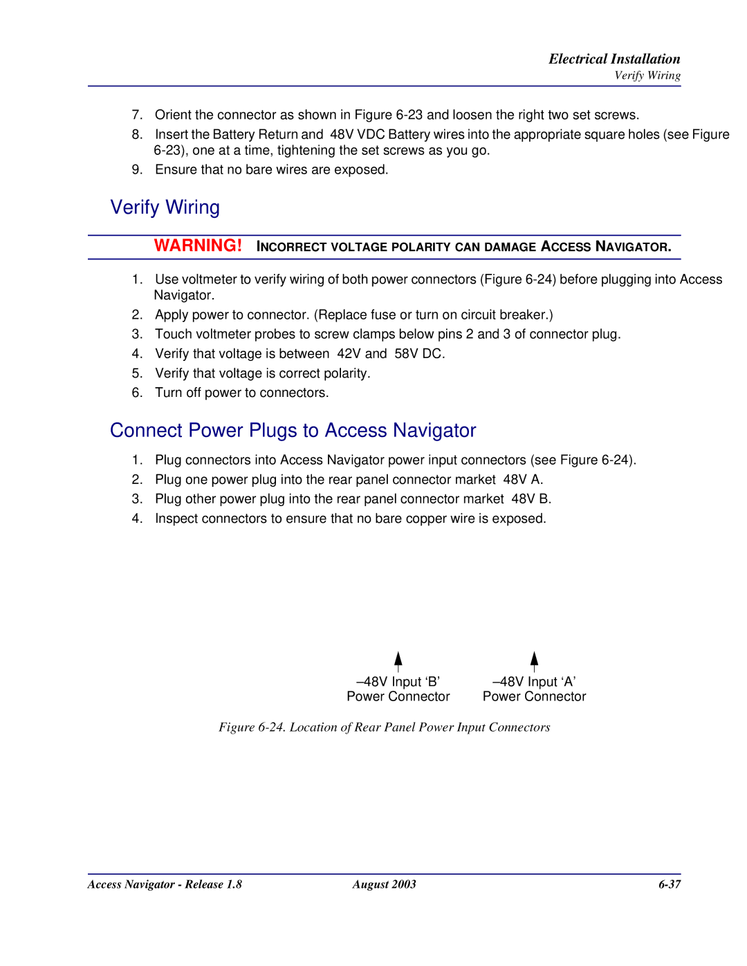
Connect Power Plugs to Access Navigator
Verify Wiring
Dress Cables and Wires
Dress Cables and Wires
Verification Summary
Acceptance Test
26. Location of Front Panel Power-On Status LEDs
Apply Power and Verify Operation
Verify DSX-1 Connections
Verify Chassis Ground Connection
Verify RS-232 Management Connection
Verify Ethernet Management Connection
Verify Ethernet Cable Connection
Set clock1 bits set clock2 bits
Verify Bits Connection
Controller ’A’ Indicators Controller ’B’ Indicators
Verify Alarm Output Connections
Electrical Installation
31. Location of Rear Panel Alarm Input Connector
Verify Alarm Input Connections
Exit
Exit Management Session
Install Redundant Controller Card
Verify Software Compatibility
33. Location of Front Panel Cover Screws
Remove Front Cover
34. Location of Controller Cards
Install Controller Card
Verify Operation
Switch controller
Replace Front Cover
Install Additional Quad T1 Framer Cards
37. Location of Front Panel Cover Screws
38. Location of Quad T1 Framer Cards
Install Quad T1 Framer Card
Eject
Set ds1 n up
Status equipment
Set ds1 n down
29-32 13-16 17-20 21-24 26-28
Configure Management Interfaces
Setup Summary
Replace Front Cover
Start RS-232 Management Session
Set Time
Set Date
Set IP Address and Subnet Mask
Set System ID or Clli code
Set Gateway Address
Exit Management Session
Start Management Session
Start Management Session
Management Requirements
Show ds1
Command Line Interface Conventions
Procedure Summary
RS-232 Management
RS-232 Management Requirements
Connect RS-232 Cable to Access Navigator
Set Up Terminal Program
Obtain Information
Start RS-232 Management Session
Exit RS-232 Management Session
Perform Management Operations
Telnet Management Requirements
Telnet Management
Start Telnet Management Session
Start Telnet Program and Connect to Access Navigator
Exit Telnet Management Session When Finished
NetworkValet EMS and Valet Management
Start Management Session
Provision Access Navigator
CLI Commands Descriptions
Provision Access Navigator
Basic Provisioning Overview
Basic Provisioning Quick Guide
Obtain Provisioning Information
Verify System Equipment Configuration
Show id
Set System ID or Clli Code
Set Time
Set Date
Show date
Show time
Set Ethernet Properties
Set ethernet ip address none
Set User and Password Security
Set user Alice password
DNVRCO1A201
Set Snmp Properties
Example Set snmp nms 1
Provision DCS Service
DCS Provisioning Overview
Provision DCS Service
Provisioning TR-08 Service with DCS
Provisioning Isdn BRI Service
Provisioning Voice Services for TR-08 Shelves B, C, and D
Provisioning Conventional TR-08 Voice Services
Special TR-08 Settings
Provisioning Enhanced Voice and Data Services
DCS Provisioning Quick Guide
Card not installed
Show ds1 all
Verify Service Status
Status ds1 n
Set ds1 n down Set ds0 nch type voicedata
Set Unused Circuits Out of Service
Set System Clock Source
CAC
Provision Groom DS1 Circuits to Network
Example Set ds1 10 loopdetect on
Provision Drop DS1 Circuits to Subscribers
Test Groom DS1 Circuits
Set ds1 20 framing esf
Provision and Connect Isdn BRI 3DS0 Channels
Provision and Connect Isdn PRI Channels
Provision and Connect DS0s
DS0 #10
Turn Up Service
Test DS1 and DS0 Circuits
Set ds1 n up set ds0 nch up
Test DS1 and DS0 Circuits
Provision GR-303 Service
GR-303 Provisioning Overview
Provision GR-303 Service
Access Navigator GR-303 Services
Provisioning P-Phone Service
Provisioning TR-08 Service to Access Banks
Provisioning TR-08 Service with GR-303 Translation
Signaling Translation
TR-08 Configuration
Special Pots Cards
CRV Numbering
Set ds0 41-24 crv 311-334 slc96
Set ds0 49-16 crv
Framing and FDL Settings
Access Bank I/TR-08 Switch Settings
Switch Shelf Access Bank I/TR-08 Loopback Code Response
GR-303 Provisioning Quick Guide
Set DS0s in service
Connect Isdn D channel to Switch
Set DS1s in service
Isdn BRI 41 TDM channels
Access Navigator Release August 10-11
10-12
Set ds1 n down set ds0 nch down
Show switch
Set System Switch Type
Provision Switch DS1s to Interface Group
10-16
Access Navigator Release August 10-17
Assign Primary and Secondary EOC
Set tmc primary nchnone
Assign Primary and Secondary TMC
Test DS1 Circuits
Provision Drop DS1 Circuits to Subscriber
Set ds1 n framing d4esfslc96
Example Set ds1 Fdl none Fdl t1403
10-24
Provision Isdn BRI 41 TDM Service to Subscribers
CRV
Show isdn database
Send switch provision request
10-28
Access Navigator Release August 10-29
Provision DS0s to Subscribers
Set ds0 nch type gr303
Assign Call Reference Values CRVs
Example Set ds0 21-4 crv
Test Circuits
Provision Remote Access Bank
Provision Remote Access Bank
Remote Access Bank II Provisioning Overview
Requirements
Pre-Provisioning and Testing
Analog Interfaces
Crossconnect Features
Crossconnections Abii
Valid Crossconnect Assignments
FX Analog Interfaces
FX Interfaces Support Analog Voice and Data Services
Fractional Interfaces
Valid Interface Assignments
Interface Type DS1 Type DS0 Type Voice Data GR-303
Remote Interfaces
Remote Access Bank II Provisioning Quick Guide
Remote Access Bank II Maintenance Quick Guide
DS1 Card Installed Card not installed
11-12
Access Navigator Release August 11-13
Temporarily Disable Configuration Downloading
Provision Drop DS1 to Remote Access Bank
Set ds1 n remote device management cafdl
Provision DS0s
Set ds0 nch type voicedatagr303
Provision DS0 Crossconnects
Example connect 2519-24
Create Fractional Interfaces if required
Configure Remote RS-232 Interface if used
Set baud rate with the following command
Configure Remote T1 Drop Interface if used
Set remote n t1drop lbo setting
Set remote n t1drop linecode amib8zs
Set remote n t1drop prm ansiatt
Configure Remote V.35 Interface if used
Set remote n v35 clkinv rxtxrxtxnone
Connect Fractional Interface to Remote Interface
Download Configuration to Remote Access Bank
Verify Downloaded Settings optional
Call Status FX and Spots To Loop or
Test Remote Circuits
Provision Remote Adit 600 via FDL
Provision Remote Adit 600 via FDL
Remote Adit 600 FDL Provisioning Overview
On-Net Customer Location Premises
FDL Management Configuration
Remote Adit 600 FDL Provisioning Quick Guide
Set
Provision Remote Adit 600 via FDL
Verify Equipment Configuration
Access Navigator Release August 12-7
Status remote nall
CA FDL
Interface
Provision Drop DS1s to Remote Adit
Set ds1 n linecode amib8zs
12-12
Provision Drop DS0s
Set ds0 nch up Example set ds0 101-24 up
Set ds0 nch signal lsgsem
Provision DS0 Crossconnects if required
Crossconnect Examples
Logon remote n
Provision Remote Adit
12-18
Provision Remote Adit 600 via IP DS0
Provision Remote Adit 600 via IP DS0
Remote IP DS0 Provisioning Overview
Carrier Access IP DS0 Management Configuration
IP DS0 Management Configuration
Remote IP DS0 Provisioning Quick Guide
Access Navigator CLI Commands Descriptions
Router Setup
Adit CLI Commands Descriptions
Router Provisioning Quick Guide
Verify status of management channel
Set Device Name to Adit1
Select the PVC Management as Disabled
Remote Adit IP DS0 Provisioning Quick Guide
13-8
Access Navigator Release August 13-9
13-10
Out of Service
Provision Groom DS1s to Adit Router
Set ds1 32 framing esf
13-14
Access Navigator Release August 13-15
Set ds1 n remote device management caip ipaddr pphone
Set ds1 n framing d4esf
Set DS1 identification
Provision Groom DS0s to Adit Router
Provision Drop DS0s to Remote Adit
13-20
Access Navigator Release August 13-21
13-22
Access Navigator Release August 13-23
13-24
Alarm Clearing
Identify Alarm Clearing Procedure
Alarm Clearing
Facility Alarm System go to Clear Alarms FDL on
CLI Critical Alarm Message and Trouble Clearing Procedure
Clear Alarms FDL
Event Message Description Trouble Clearing Procedure
Set alarms critical off
Set ds1 n updown
CLI Major Alarm Message and Trouble Clearing Procedure
Card Software on
CLI Minor Alarm Message and Trouble Clearing Procedure
Show eoc
Status eoc
Show tmc
Status tmc
EOC Critical Alarm Message and Trouble Clearing Procedure
Clear Alarms EOC
EOC Major Alarm Message and Trouble Clearing Procedure
EOC Minor Alarm Message and Trouble Clearing Procedure
Active
14-12
Switch
EOC Warning Alarm Message and Trouble Clearing Procedure
Clear Alarms Snmp
Trap Message and Trouble Clearing Procedure
Trap Message Description Trouble Clearing Procedure
Alarm Indicators
Clear Alarms Status Indicators
Power Status LEDs
Power Status LEDs
LED State Description Troubleshooting
System, use the switch controller
Status equipment command for
Active/Standby Controller Status LEDs
10. Active/Standby Controller Status LEDs
Major Alarm Status LEDs
Critical Alarm Status LEDs
11. Critical Alarm Status LEDs
12. Major Alarm Status LEDs
Alarm Cutoff ACO Status LED
Minor Alarm Status LEDs
13. Minor Alarm Status LEDs
14. Alarm Cutoff ACO Status LEDs
Set ds1 up command
DS1 Status LEDs
15. DS1 Status LEDs
16. Ethernet Link Status LED
Ethernet Link Status LED
14-22
Diagnostics & Troubleshooting
Alarms and Logs
Diagnostics & Troubleshooting
Operations Interface
Alarm Testing
Alarm Reporting
Alarm and Status Indicators
Syntax set alarms criticalmajorminor onoff
Facility Alarm System
Alarm Cutoff ACO
Alarm Signaling Red, Yellow RAI, Blue AIS
DS1 Failures
Event Log
Syntax log majorminoralertinfo
Configuration Change Log
TMC Log
Bert Log
Syntax clear bert log
Syntax log tmc permanent
Indicator Locations
Alarm and Status Indicators
Rear Panel Ethernet Indicator
Indicator Descriptions
Indicator Descriptions
State Description
Green
Status and Performance
Status Clock
Syntax status clock
Status DS0
Syntax status ds0 nch
Example status ds0
Syntax status ds1 n
Status DS1
Field Description
Example status ds1
Syntax status ds1 all
Status DS1 All
Access Navigator Release August 15-15
Status DS1 Performance
Syntax status ds1 n performance
Example status ds1 9 performance
Status DS1 Performance History
Syntax status ds1 n performance history
Example status ds1 9 performance history
Syntax clear ds1 n performance
Clear DS1 Performance
Syntax status equipment
Status Equipment
Syntax status ip
Status IP
Syntax status remote nall
Status Remote
Field
Example status remote all
Status CRV
GR-303 Status and Performance
Syntax status crv range
Example status crv
Status Isdn CRV
Syntax status isdn crv range
Example status isdn crv
15-24
Status TMC
Status EOC
Syntax status eoc
Syntax status tmc
Originating Calls Blocked Calls Secondary
Status TMC History
Syntax status tmc allinterval
Example status tmc all
Clear Peak Call Count
Clear Blocked Call Count
Clear Permanent Call Count
Set CRV Idle
DS1 Loopdetect
Near-End Loopbacks
DS1 FDL Protocol
Syntax set ds1 n loopdetect onoff
DS1 Payload Loopback
DS1 Line Loopback
Syntax set ds1 n line loopdownloopup
Syntax set ds1 n payload loopdownloopup
Far-End Loopbacks
DS1 CSU Loopup
Syntax send ds1 n csu loopuploopdown
Syntax send ds1 n line loopuploopdown
DS1 Line Loopup
Syntax send ds1 n network loopuploopdown
DS1 Network Loopup
Syntax send ds1 n niu loopuploopdown
DS1 NIU Loopup
Syntax send ds1 n payload loopuploopdown
DS1 Payload Loopup
Read Remote Loopback
Access Bank II Loopbacks
Send Remote Loopdown
Syntax read remote n loopback
Send Remote RS232 TSI Equipment Loopup
Send Remote RS232 Line Loopup
Syntax send remote n rs232 line loopup
Syntax send remote 9 rs232 tsi equipment loopup
Send Remote Sdsl Payload Loopup
Send Remote RS232 TSI Network Loopup
Syntax send remote 9 rs232 tsi network loopup
Syntax send remote n sdsl payload loopup
Send Remote T1 TSI Loopup
Send Remote T1 Payload Loopup
Syntax send remote n t1 payload loopup
Syntax send remote n t1 tsi loopup
Send Remote T1 Drop Payload Loopup
Send Remote T1 Drop Line Loopup
Syntax send remote n t1drop line loopup
Syntax send remote n t1drop payload loopup
Send Remote V35 Line Loopup
Syntax send remote n t1drop tsi loopup
Syntax send remote n v35 line loopup
Send Remote V35 TSI Network Loopup
Send Remote V35 TSI Equipment Loopup
Syntax send remote n v35 tsi equipment loopup
Syntax send remote n v35 tsi network loopup
Send DS1 Pattern Off
Bit Patterns and Error Tests
Send DS1 Line Pattern
Syntax send ds1 n off
Syntax send ds1 n line p2e11p2e15p2e23qrss
Send DS1 Payload Pattern
Access Navigator Payload Code
Send DS1 Line Pattern with BER Test
Example set ds1 9 line p2e15 test
Syntax send ds1 n line p2e11p2e15p2e23qrss test
FBE
26. Send DS1 Payload Pattern with BER Test
Send DS1 Payload Pattern with BER Test
Example send ds1 9 payload p2e15 test
Test
Example
15-52
Other Maintenance Commands
Load tftp config ipaddr file
Show users
Whoami
Show isdn database show crv database
Technical Support
Let run for 2 or 3 minutes
Trace tmc on
Trace tmc off Trace eoc
Trace eoc Off
Maintenance Procedures
Maintenance Procedures
Repair and Return Procedure
Overview
Replace Controller Card
Tools and Materials Required
Verify Equipment Status
Determine Which Replacement Procedure to Use
Procedure Summary
Precautions
Replace Protected Controller Card
Verify Compatibility
Remove Front Cover
Location of Controller Cards
Replace Standby Controller
Installing and Removing Controller Card
Verify Operation and Compatibility
Replace Other Controller Card
Replace Unprotected Controller Card
Controller B Active DS1 Card Installed
Access Navigator Release August 16-15
Insert New Controller
Access Navigator Release August 16-17
Remove Old Controller
Replace Quad T1 Framer Card
Overview
QF Card Slot DS1 Circuit Numbers
Tools and Materials Required
Temporarily Move Clock Sources if required
Verify Equipment Status
Set clock1 ds1 n
Set clock2 ds1 n
Location of Front Panel Cover Screws
10. Location of Quad T1 Framer Cards
Replace Quad T1 Card
11. Installing Quad T1 Framer Card
Verify Operation
12. Location of Front DS-1 Status Indicators
Show clock
Restore Clock Sources if required
Install Simm on Controller Card
Precautions Tools and Materials Required
16-30
Standby Controller ACTIVE/STANDBY indicator is off
14. Location of Front Panel Cover Screws
15. Location of Controller Cards
Install Simm
Simm
Access Navigator Release August 16-35
16-36
Update Controller Card Software
Update Controller Card Software
Download Procedures
Update Software via Tftp Two Controllers
Tftp Requirements
Event Log
17-4
Information and Materials Required
Install Optional Tftp Server Software
Requirement One Controller is in Standby
Status equipment all
Verify IP Connectivity
Upload Configuration
Download Software
Show ds0
Set ds0 321 up set ds0 321 down
Set ds0 321 down set ds0 321 up
Example load tftp config 192.168.118.65 AN26
Download Configuration
Xmodem Requirements
Update Software via Xmodem Two Controllers
17-12
Access Navigator Release August 17-13
System
Access Navigator Release August 17-15
17-16
Update Software via Xmodem One Controller
17-18
SW Build Number 17701 Boot Code Revision 01.09
Minutes
Access Navigator Release August 17-21
17-22
CLI Language Reference
CLI Language Reference
CLI Access Via RS-232 and Telnet
CLI Requirements
Port settings
CLI over RS-232
Terminal emulation
CLI over Telnet
Access Navigator IP address
RS-232 interface for modem connection
Ethernet interface
Using CLI Command Scripts
Character and Line Delays
Confirmations and Errors
Commands, Confirmations, and Error Messages
Command Categories
CLI Conventions and Shortcuts
SystemID set ds1 24 framing esf
Text Conventions
SystemID set ds1 42 framing esf
Set ds1 1-4 up
Command Syntax Descriptions
Command Shortcuts Tabbing
Entering DS1 and DS0 Numbers and Ranges
Keyboard Shortcuts
Displaying Basic Commands
Online Help
Help System Overview
Context Sensitive Help
18-12
Syntax print help
Printing the Help File
Administration
Users and Passwords
Access Levels
User Level Access
Who Am
Managing Users
Show Users
Syntax show users
Set User Access Level
Add User
Syntax add user name Example add user alice
Delete User Password
Set User Password
Access Definition
Delete User
Login with No User Name Required
Logging In and Out
Startup Message
Login with User Name Required
Login with No Password Required
Login with Password Required
Logout Exit
Autoexit CLI Session Timeout
Syntax set autoexit minutes
Example set autoexit
ACO
CLI Command List
CLI Language Reference
Add Interface
ACO
Type Description
Remote Port Maximum Number of DS0s
Alarms
Syntax alarms majorminoralert
Syntax add user name
Syntax alarms ds1 nall majorminoralert
Syntax alarms ds1 nall
Syntax alarms equipment
Syntax alarms equipment majorminoralert
Clear Bert Log
Clear Config Log
Clear Blocked Call Count
Clear DS1 Performance
Clear Peak Call Count
Clear Log
Clear Permanent Call Count
Clear Remote Log
Example connect 2519-24
Connect
18-30
Drop Groom Switch
Connect Remote Interface
Drop
Syntax connect remote name fxrs232sdslt1dropv35
Delete Interface
Syntax delete interface name
Example delete interface AcmeV35
Syntax delete user name
Disconnect
Syntax disconnect nch
Example disconnect
Exit
Disconnect Remote
Exit Remote Session Ctrl+C
Syntax disconnect remote name
Xmodem
Load
Active
Load Tftp Config
Log
Example load tftp config 192.168.118.65 AN26
Example log equipment minor
Example log Message
Log Bert
Example log config ds0
Log Config
Description
Example log config
Example log tmc Message
Log TMC
Logon Remote
Syntax logon remote n
Example logon remote
Syntax read remote n alarms
Read Remote Alarms
Example read remote 9 alarms
Ping
18-46
Access Navigator Release August 18-47
Read Remote Connections
Syntax read remote n connections
Example read remote 9 connections
Access Navigator Release August 18-49
Read Remote Log
Syntax read remote n log
Example read remote 9 log
Read Remote RS232
Read Remote Loopback
Example read remote 9 loopback
Syntax read remote n rs232
Syntax read remote n t1t1drop performance
Read Remote Performance
Access Navigator Release August 18-53
Syntax read remote n t1
Read Remote T1
Level 3 monitor
Read Remote T1drop
Read remote
Read remote T1drop
Read Remote
Syntax read remote n
Example read remote 9
Reset DS1 Framer
Reset All
Syntax reset all
Syntax reset ds1 n
Reset Standby
Reset Remote
Syntax reset remote n
Example reset remote
Default Settings
Restore Defaults
Syntax restore defaults
Parameter Default Comments
Normal
CLI Language Reference
Line loopback deactivate
Send DS1 CSU Loopup
Send DS1 Line Loopup
Example send ds1 9 csu loopup
Example send ds1 9 csu loopdown
00001110 11111111
Send DS1 Line pattern
Example send ds1 9 line loopup
Example send ds1 9 line loopdown
Send DS1 Line Pattern
Example set ds1 9 line p2e15
Send DS1 Line pattern Test
Send DS1 Line Pattern with BER Test
Access Navigator Release August 18-69
Send DS1 Network Loopup
Send DS1 Network Loopup
Send DS1 NIU Loopup
Example send ds1 9 network loopup
Example send ds1 9 network loopdown
Example send ds1 9 niu loopup
Syntax send ds1 n niu loopup loopdown
Example send ds1 9 niu loopdown
Send DS1 Payload Loopup
Example send ds1 9 payload loopdown
Example send ds1 9 payload loopup
Send DS1 Payload pattern
10. Send DS1 Payload Pattern
Example send ds1 9 payload p2e15
Send DS1 Payload pattern Test
11. Send DS1 Payload Pattern with BER Test
P2e11
Example set ds1 9 payload p2e15 test
Example send ds1 9 payload f1in8 test
Send Remote Loopdown
Send DS1 Off
Example send ds1 9 off
Example send remote 9 loopdown
Example send remote 9 rs232 line loopup
Send Remote RS232 Line Loopup
Send Remote RS232 TSI Loopup
Syntax send remote n rs232 tsi equipmentnetwork loopup
Send Remote Sdsl Payload Loopup
Example send remote 9 sdsl payload loopup
Send Remote T1 Payload Loopup
Example send remote 9 t1 payload loopup
Send Remote T1 TSI Loopup
Example send remote 9 t1 tsi loopup
Remote loopdown command
Example send remote 9 t1drop line loopup
Send Remote T1Drop Line Loopup
Send Remote T1Drop Payload Loopup
Example send remote 9 t1drop payload loopup
Send Remote T1Drop TSI Loopup
Example send remote 9 t1drop tsi loopup
Send Remote V35 Line Loopup
Example send remote 9 v35 line loopup
21. Remote V.35 Line Loopup
Send Remote V35 TSI Loopup
Send Switch Provision Request
Syntax send switch provision request
Syntax send remote n v35 tsi equipmentnetwork loopup
Set Alarms
Example set alarms major on
Set Autoexit
Syntax set clock1clock2 setting
Setting Description
Set Clock
Set CRV Idle
Set Date
Set DS0 CRV
Syntax set ds0 nch crv range slc96
513 crv
Ds0 49-16 Crv 111-118
Ds0 41-24 Crv 311-323
26. DS0s Assigned to CRVs in Odd-Even Order
Syntax set ds0 nch isdn none
Set DS0 Isdn BRI CRV
Syntax set ds0 nch pphone Syntax set ds0 nch pphone none
Set DS0 P-Phone
Set DS0 Service
Syntax set ds0 nch updown
Example set ds0 131-16 up
Syntax set ds0 nch signal didemgsgshrgls
Set DS0 Signal
Set DS0 Type
27. Signaling Used in Common Applications
Set DS1 Clock
Set DS1 FDL
Syntax set ds0 nch type datavoicegr303
Permissible Selections
Application Configuration Requirements
Application
Framing
Example set ds1 12 fdl none Example set ds1 12 fdl t1403
Set DS1 Framing
Syntax set ds1 n framing d4esfslc96
Example set ds1 9 framing esf
Set DS1 ID
Set DS1 LBO
Set DS1 Line Loopup
Example set ds1 9 line loopdown
Set DS1 Linecode
Syntax set ds1 n linecode amib8zs
Example set ds1 9 linecode b8zs
Example set ds1 9 loopdetect off
Set DS1 Loopdetect
Set DS1 Payload Loopup
Syntax set ds1 n payload loopuploopdown
Example set ds1 9 payload loopdown
Example set ds1
Set DS1 Remote Device Mgmt
Mgmt ds1
Mgmt caip
Set DS1 TermID
Set DS1 Service
Syntax set ds1 n updown
Example set ds1 9 up
Set DS1 Threshold
Syntax set ds1 n termid id
Example set ds1 5 termid
Syntax set ds1 n type dropgroomswitch
Set DS1 Type
Set EOC
Set Ethernet IP Address
Syntax set eoc primarysecondary nchnone
Syntax set ethernet ip address address mask
Set ID
Set IP Gateway Address
Example set id Acme Corp. AN#2 Example set id DNVRCO1A201
Set Remote Config
Syntax set ip gateway address
Example set ip gateway Example set ip gateway none
Set Remote RS232 Baud
Set Remote ID
Set Remote RS232 Stop
Set Remote RS232 Data
Set Remote T1Drop Framing
Syntax set remote n t1drop framing d4esf
Example set remote 9 t1drop framing d4
Set Remote T1Drop Linecode
Set Remote T1Drop LBO
Set Remote V35 ClockInv
Set Remote T1Drop PRM
Set Remote V35 Data
Set Remote V35 CTS
Set Remote V35 DSU
Set Remote V35 RxClock
Set Remote V35 Speed
Syntax set remote n v35 speed
Set Screen
Example set remote 9 v35 speed nx64
Syntax set screen heightoff
Set Snmp GetCom
Set Snmp Contact
Set Snmp Name
Set Snmp Location
Set Snmp SetCom
Set Snmp NMS Address
Set Snmp TrapCom
Set Switch Type
Set TMC
Set Time
Syntax set time hhmmss
Example set time
Set User Level
Syntax set user name level access
Syntax set user name password
Show Clock
Show Autoexit
Show Connect
Syntax show autoexit
Example show connect
Syntax show connect n
Show CRV
Syntax show crv range
Example show crv
30. Factory Default Call Reference Values
Show DS0
Show Date
Syntax show date
Syntax show ds0 nch
Show DS1
Syntax show ds1 n
Example show ds1
Access Navigator Release August 18-141
Remote Device Mgmt on
Performance Description Thresholds
Syntax show ds1 all
Show DS1 All
18-144
Show EOC
Show Ethernet
Syntax show ethernet
Show Interface
Show ID
Example show interface AcmeT1 Example show interface all
Syntax show interface nameall
Show Isdn CRV
Show IP
Example show isdn crv
Syntax show isdn crv range
Show Remote
Syntax show remote nall
Example show remote Example show remote all
Show Remote Connections
Syntax show remote n connections
Example show remote 9 connections
18-152
Syntax show snmp
Show Snmp
Switch Setting Description
Show Switch
Show Time
Show TMC
Access Navigator Release August 18-155
Status Clock
Status CRV
Status DS0
Status DS1
18-160
Status DS1 All
Status DS1 Performance
Access Navigator Release August 18-163
18-164
Status DS1 Performance History
UAS
Status EOC
Syntax status equipment all Example status equipment
Status Equipment
Example status equipment all
Status IP
Status Isdn CRV
Status Remote
Status TMC
Pots
Syntax status tmc allintervalrange
Status TMC History
Switch Controller
Upload Tftp Config
Syntax switch controller
WhoAmI
Example upload tftp config 192.168.118.65 CAN26
18-178
Appendix
Remote Digital Customer Premises Terminal RDT
EOC Interface
Access Navigator Release August
Managed Object Class Support
Alarm Count List Objects on page A-5
Table A-2 Alarm Count List Objects
Alarm Count List Objects
Attribute Support Command Support Create Get Set Delete
Analog Line Termination Objects
DS1 Framed Path Termination Objects
DS0 Channel Termination Objects
Table A-3 DS0 Channel Termination Objects
Table A-4 DS1 Framed Path Termination Objects
EBS Line Termination Objects
DS1 Line Termination Objects
Table A-5 DS1 Line Termination Objects
Table A-6 DS1 Line Termination Objects
Isdn Framed Path Termination Objects
Isdn Line Termination Objects
Table A-7 Isdn Line Termination Objects
Table A-8 Isdn Framed Path Termination Objects
Isdn Framed Path Termination Objects
Crossconnection
Quarter DS0 Channel Termination
Table A-9 Isdn Framed Path Termination Objects
Table A-10 Crossconnection
Idlc Call Processing Profile Objects
Equipment Objects
Table A-11 Equipment Objects
Table A-12 Idlc Call Processing Profile Objects
Table A-13 Idlc Data Link Profile Objects
Idlc Data Link Profile Objects
Table A-14 Idlc Data Link Termination Objects
Idlc Data Link Termination Objects
Memory Objects
Idlc Terminal Objects
Table A-15 Idlc Terminal Objects
Table A-16 Memory Objects
Protection Group Objects
Network Element Objects
Table A-17 Network Element Objects
Table A-18 Protection Group Objects
Table A-19 Protection Group Unit Objects
Protection Group Unit Objects
Actions
Table A-20 Action Support
Managed Object Class Action Support
Notifications
Table A-21 Event Report Notification
Managed Object Class Event Report Notification
FDL Interface
Figure B-1. FDL Interface
FDL Interface
Access Bank II Remote Provisioning Requirements
Access Navigator Remote Provisioning Requirements
Remote Provisioning Requirements
Adit 600 TDM Remote Provisioning Requirements
Access Bank II Capabilities
Access Bank II Capabilities
Interface Capabilities and Settings
Remote Provisioning Capabilities
RTS
FDL Interface
Snmp Interface
Operations Location Center
Snmp Interface
Figure C-2. Carrier Access Enterprise MIB top level
Carrier Access Enterprise MIB
MIB Structure
Snmp Basics
MIB Tables
Table C-1.Standard Snmp Object Types
Object Type Description
Managing Networks
Table C-2 Standard Snmp Messages
Message Type Description
Snmp Protocols
Snmp Requirements
Table C-3 Snmp Configuration Items
Table C-4 Standard Snmp Trap Reports
Snmp Trap Reports
Table C-5 Enterprise Snmp Trap Reports
Trap Description Test Method
Snmp Interface
Glossary
LTE
Glossary
Lult
Definitions
Page
Identifier
Access Navigator Release August GlossaryGlossary-7
Electronic Business Set Or Service
Access Navigator Release August GlossaryGlossary-9
Multiplex
POP RAI
Stratum
Wide Area Network Wideband
GlossaryGlossaryGlossaryGlossary-14 August
Index
EOC
Index
Access Navigator Release August Index
CPE
DLC
LED
FXO
TMC
LAN
T1 TSI
MIB
Index
PRI
Sdsl
DS1
CRV Isdn BRI CRV Phone Service Signal Type
DSU
SPR
Tftp
TSI
Index
Index