Chapter 18 Fault Management
Cisco 12000/10720 Router Trap Support
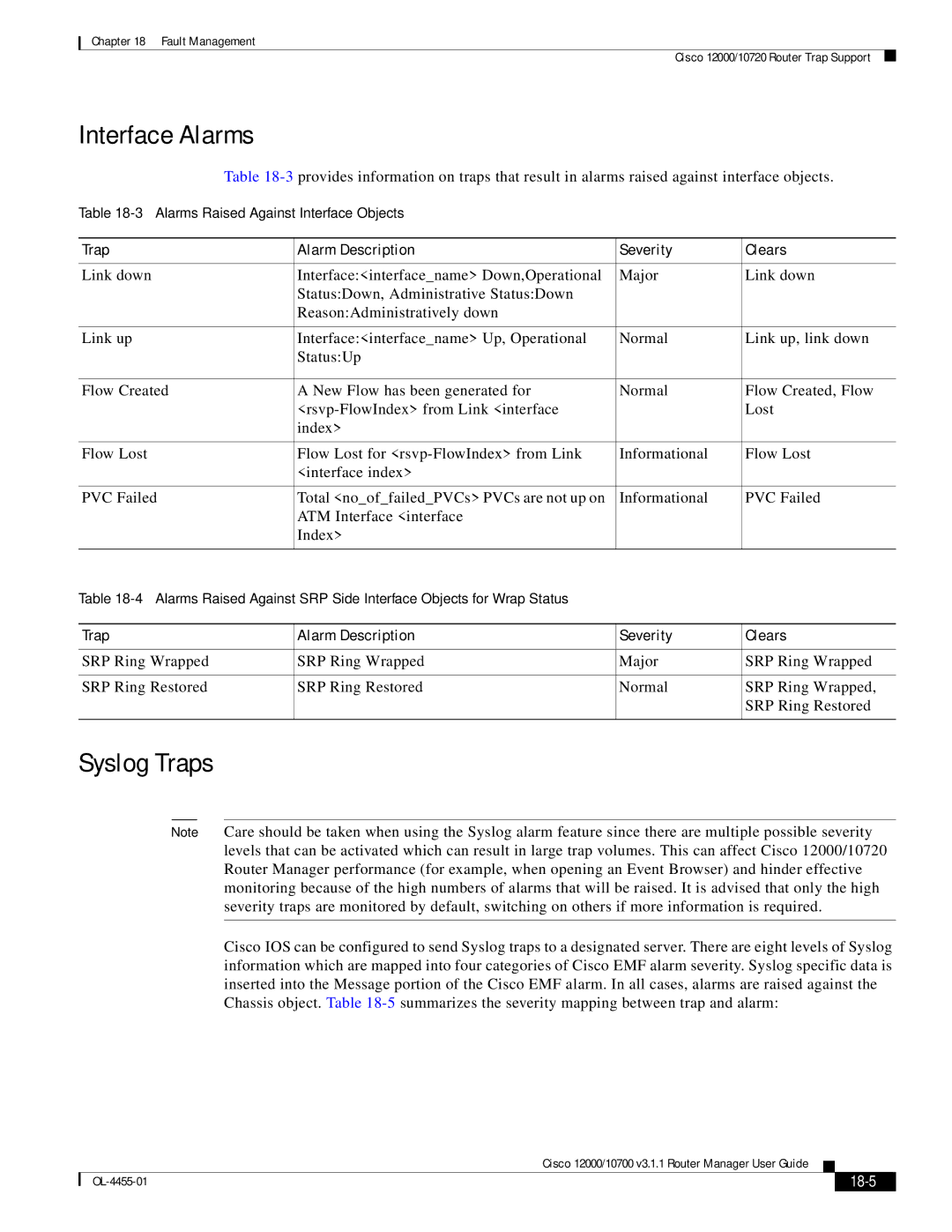
Interface Alarms
Table
Table
Trap | Alarm Description | Severity | Clears |
|
|
|
|
Link down | Interface:<interface_name> Down,Operational | Major | Link down |
| Status:Down, Administrative Status:Down |
|
|
| Reason:Administratively down |
|
|
|
|
|
|
Link up | Interface:<interface_name> Up, Operational | Normal | Link up, link down |
| Status:Up |
|
|
|
|
|
|
Flow Created | A New Flow has been generated for | Normal | Flow Created, Flow |
|
| Lost | |
| index> |
|
|
|
|
|
|
Flow Lost | Flow Lost for | Informational | Flow Lost |
| <interface index> |
|
|
|
|
|
|
PVC Failed | Total <no_of_failed_PVCs> PVCs are not up on | Informational | PVC Failed |
| ATM Interface <interface |
|
|
| Index> |
|
|
|
|
|
|
Table |
|
| |
|
|
|
|
Trap | Alarm Description | Severity | Clears |
|
|
|
|
SRP Ring Wrapped | SRP Ring Wrapped | Major | SRP Ring Wrapped |
|
|
|
|
SRP Ring Restored | SRP Ring Restored | Normal | SRP Ring Wrapped, |
|
|
| SRP Ring Restored |
|
|
|
|
Syslog Traps
Note Care should be taken when using the Syslog alarm feature since there are multiple possible severity levels that can be activated which can result in large trap volumes. This can affect Cisco 12000/10720 Router Manager performance (for example, when opening an Event Browser) and hinder effective monitoring because of the high numbers of alarms that will be raised. It is advised that only the high severity traps are monitored by default, switching on others if more information is required.
Cisco IOS can be configured to send Syslog traps to a designated server. There are eight levels of Syslog information which are mapped into four categories of Cisco EMF alarm severity. Syslog specific data is inserted into the Message portion of the Cisco EMF alarm. In all cases, alarms are raised against the Chassis object. Table
Cisco 12000/10700 v3.1.1 Router Manager User Guide
|
|
| |
|
|