A P P E N D I X C
Investigating LSP Black Holes Using Cisco 12000 Series Router Manager
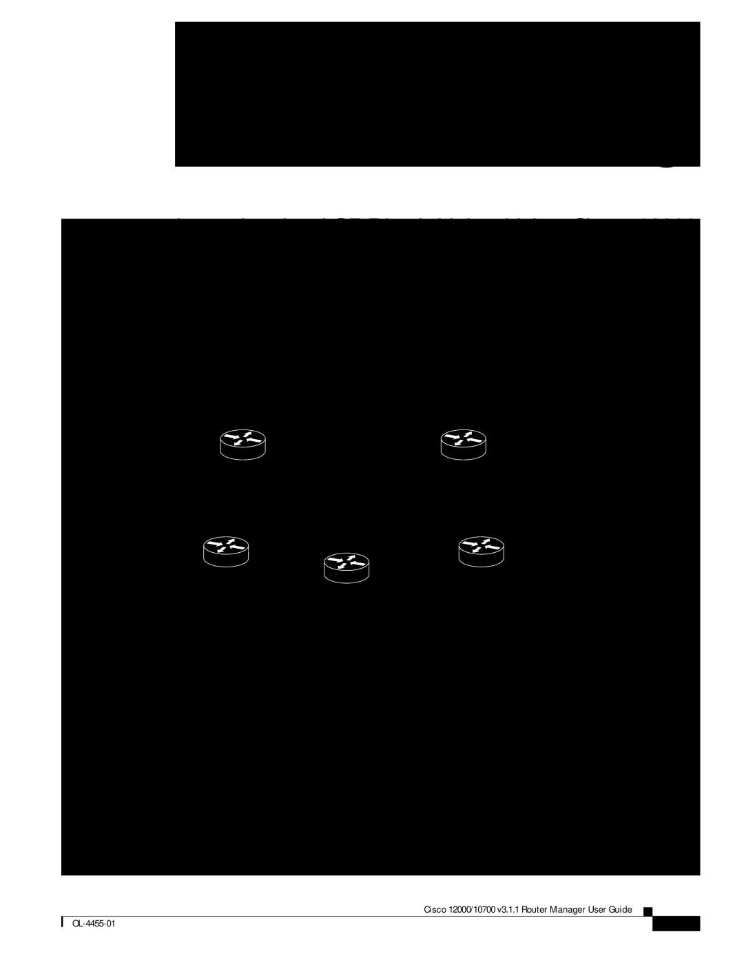
Network Diagram
Figure |
|
|
|
|
|
|
| |||||||||||||
|
|
|
|
|
|
|
|
|
|
|
| 192.168.1.196/26 |
| |||||||
|
|
|
|
|
|
| CE1 |
|
|
| CE2 |
|
|
|
|
|
|
| ||
|
|
|
|
|
|
|
|
|
|
|
|
| ||||||||
|
|
|
|
|
|
|
|
|
|
|
|
| .6 |
|
|
|
|
| ||
|
|
|
| .1 |
|
|
|
|
|
|
|
|
|
|
|
|
| |||
|
|
|
|
|
|
| 10.1.1.0/24 |
| 10.10.10.0/24 |
|
|
|
|
|
|
| ||||
10.2.2.2 |
|
| .2 |
|
|
| .5 |
|
|
| ||||||||||
|
|
|
|
|
|
| 10.7.7.7 |
|
|
| 10.5.5.5 | |||||||||
|
|
|
|
|
|
|
|
|
| |||||||||||
|
|
|
|
|
|
|
|
|
|
|
|
|
|
| ||||||
|
|
|
|
|
|
|
|
|
|
|
|
|
|
|
| |||||
|
|
|
|
|
| .2 |
|
|
|
|
|
| .5 |
|
|
| ||||
|
|
|
|
|
|
| .7 |
|
|
| .7 |
|
|
|
|
|
|
| ||
|
|
|
|
|
|
|
|
|
|
|
|
|
|
|
|
|
| |||
| PE1 |
|
|
|
|
|
|
|
| PE2 |
| |||||||||
|
|
|
|
|
|
|
|
|
|
|
|
| ||||||||
|
|
|
|
|
|
|
|
|
|
|
|
| ||||||||
10.6.6.0/24 |
| P |
|
|
| 93226 | ||||||||||||||
|
|
|
|
|
|
|
|
|
|
|
|
|
|
|
|
|
| |||
|
|
|
|
|
|
|
|
|
|
|
|
|
|
|
|
| ||||
Setup
On a U10 running the Solaris 8 operating system, the following was installed:
•Cisco EMF 3.2 with required patches
•Cisco 12000/10720 Router Manager
A Cisco 12000/10720 Router Manager chassis was deployed with the IP address of the P router as shown in Figure
•
•
Cisco 12000/10700 v3.1.1 Router Manager User Guide
| ||
|