TIMEPLATE | Timing Command Dictionary |
|
|
Examples
Example 1 shows a timeplate that illustrates many of the possible statements:
TIMEPLATE “tp1” = |
|
FORCE_PI | 0; |
SKEW_FORCE_PI “cntrl” | 50; //bidi control pin |
BIDI_FORCE_PI | 70; |
MEASURE_PO | 90; |
CAPTURE_CLOCK_ON | 100; |
CAPTURE_CLOCK_OFF | 200; |
SKEW_CAPTURE_CLOCK_ON “lssd_b” | 200; |
SKEW_CAPTURE_CLOCK_OFF “lssd_b” | 225; |
PERIOD | 250; |
END; |
|
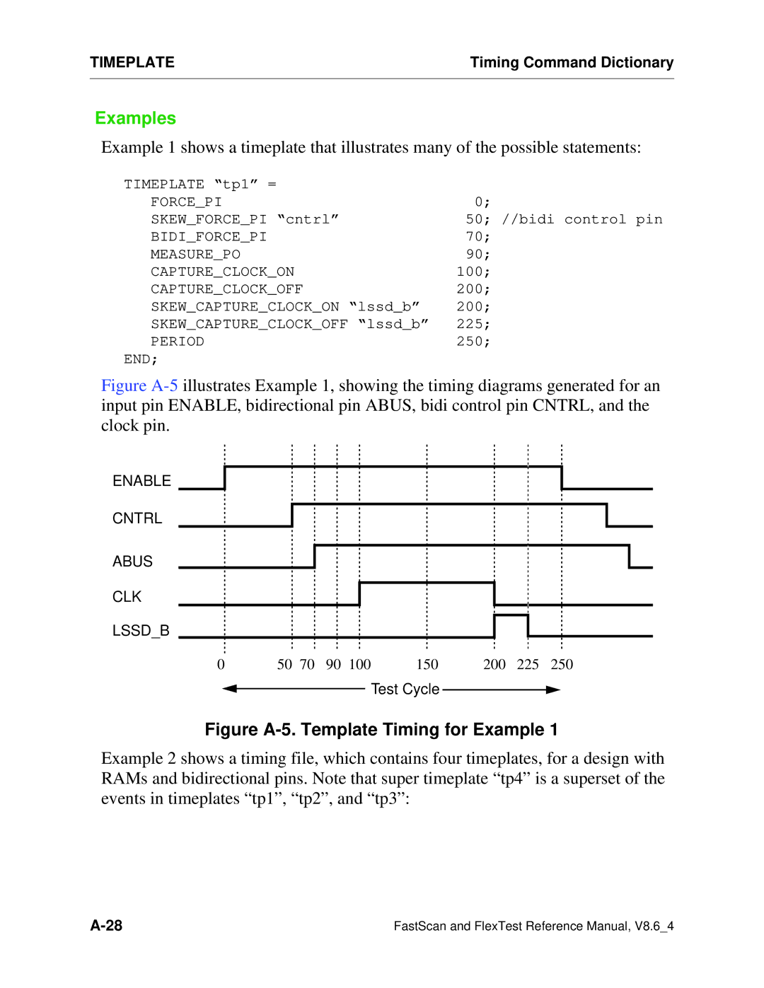
Figure A-5 illustrates Example 1, showing the timing diagrams generated for an input pin ENABLE, bidirectional pin ABUS, bidi control pin CNTRL, and the clock pin.
ENABLE
CNTRL
ABUS
CLK
LSSD_B
0 | 50 | 70 | 90 | 100 | 150 | 200 | 225 | 250 |
Test Cycle
Figure A-5. Template Timing for Example 1
Example 2 shows a timing file, which contains four timeplates, for a design with RAMs and bidirectional pins. Note that super timeplate “tp4” is a superset of the events in timeplates “tp1”, “tp2”, and “tp3”:
FastScan and FlexTest Reference Manual, V8.6_4 |