FlexTest WDB Translation Support | Using wdb2flex Effectively |
|
|
4.For each clock pin, set up return pin constraints corresponding to the control file (SR0, SR1, R0, R1), with an offset value equal to the timeframe at which the clock goes active. The pulse width should correspond to the difference between the timeframe at which the clock goes inactive and the timeframe at which the clock goes active.
For the example in Figure
add pin constraints clk sr0 1 0 1
5.For all output pins, specify the strobe timeframe corresponding to the strobe time in the control file. For the example in Figure
setup pin strobes 1
0 | 50 70 90100 | 150 | 200 | 250 | |
ENABLE |
|
|
|
|
|
ABUS |
|
|
|
|
|
CNTRL |
|
|
|
|
|
CLK |
|
|
|
|
|
OPA |
|
|
|
|
|
| 75 | 105 |
| 205 |
|
t1 |
| t2 |
| t3 |
|
| Frame 0 |
| Frame 1 | Frame 2 | |
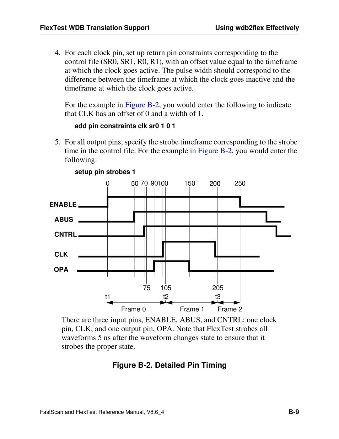
There are three input pins, ENABLE, ABUS, and CNTRL; one clock pin, CLK; and one output pin, OPA. Note that FlexTest strobes all waveforms 5 ns after the waveform changes state to ensure that it strobes the proper state.
Figure B-2. Detailed Pin Timing
FastScan and FlexTest Reference Manual, V8.6_4 |