H3C MSR 20/30/50 Series Routers
3Com Corporation Campus Drive Marlborough, MA USA
United States Government Legend
Contents
General Ethernet Interface Configuration Commands
Adsl Interface Configuration Commands
POS Interface Configuration Commands
Fundamental Serial Interface Configuration Commands
Fundamental CE1/PRI Interface Configuration Commands
Fundamental CT1/PRI Interface Configuration Commands
14 E1-F Interface Configuration Commands
Fundamental CT3 Interface Configuration Commands
15 T1-F Interface Configuration Commands
Fundamental CE3 Interface Configuration Commands
DCC Configuration Commands
Isdn BRI Interface Configuration Commands
ATM Configuration Commands
Basic Dlsw Configuration Commands
340
Frame Relay Configuration Commands
Hdlc Configuration Commands
Garp Configuration Commands
Gvrp Configuration Commands
Lapb and X.25 Configuration Commands
455
425 Display x25 hunt-group-info Display x25 map 426
451 X25 pvc X25 queue-length 453 X25 receive-threshold 454
Modem Configuration Commands
Link Aggregation Configuration Commands
Link Aggregation Debugging Commands
Port Mirroring Configuration Commands
Pppoe Client Configuration Commands
PPP Link Efficiency Mechanism Configuration Commands
Pppoe Server Configuration Commands
Isdn Configuration Commands
PPP Debugging Commands
Bridging Configuration Commands
Debugging ppp
Mstp Configuration Commands
Voice Vlan Configuration Commands
Vlan Configuration Commands
PORT-BASEDVLAN Configuration Commands
Port Isolation Configuration Commands
Cpos Interface Configuration Commands
ARP Configuration Commands
Authorized ARP Configuration Commands
Gratuitous ARP Configuration Commands
ARP Source Suppression Configuration Commands
Proxy ARP Configuration Commands
Dhcp Snooping Configuration Commands
Dhcp Relay Agent Configuration Commands
Dhcp Client Configuration Commands
Bootp Client Configuration Commands
IP Addressing Configuration Commands
DNS Configuration Commands
IP Accounting Configuration Commands
IP Performance Configuration Commands
Urpf Configuration Commands
IP Unicast Policy Routing Configuration Commands
UDP Helper Configuration Commands
Fast Forwarding Commands
Display natpt address-group 863
NAT-PT Configuration Commands
840 Display tcp ipv6 status 842
Display natpt aging-time 864 display natpt all
69 IPV6 Unicast Policy Routing Configuration Commands
Dual Stack Configuration Commands
Tunneling Configuration Commands
Terminal Access Configuration Commands
IP Routing Table Commands
BGP Configuration Commands
981 Log-peer-change
Ebgp-interface-sensitive
977
983 Peer advertise-communityBGP/BGP-VPN instance view
BGP Debugging Commands
IS-IS Configuration Commands
IS-IS Debugging Commands
Ospf Configuration Commands
1128
1155 Snmp-agent trap enable ospf
1117
1140
1179
RIP Configuration Commands
Routing Policy Common Configuration Commands
Static Routing Configuration Commands
79 IPV4 Routing Policy Configuration Commands
80 IPV6 Routing Policy Configuration Commands
82 IPV6 BGP Configuration Commands
1246
1223
1243
83 IPV6 IS-IS Configuration Commands
84 IPV6 OSPFV3 Configuration Commands
Multicast Routing and Forwarding Configuration Commands
85 IPV6 Ripng Configuration Commands
86 IPV6 Static Routing Configuration Commands
Delete ipv6 static-routes all 1325 ipv6 route-static
Cache-sa-enable 1365 display msdp brief
Igmp Configuration Commands
Msdp Configuration Commands
1366
PIM Configuration Commands
1376
1429
1421
1422
1451
MLD Configuration Commands
93 IPV6 PIM Configuration Commands
Display multicast-domain vpn-instance share-group
Multicast VPN Configuration Commands
1495
1505
Mpls Basics Configuration Commands
Mpls TE Configuration Commands
Mpls rsvp-te reliability 1610 Mpls rsvp-te resvconfirm 1611
Mpls L2VPN Configuration Commands
Mpls L3VPN Configuration Commands
VAM Server Configuration Commands
1697
Dvpn Tunnel Configuration Commands
VAM Client Configuration Commands
Ipsec Profile Configuration Commands
GRE Configuration Commands
Line Rate Configuration Commands
Traffic Policing TP Configuration Commands
Traffic Shaping Configuration Commands
Defining Class Commands
CQ Configuration Commands
Fifo Queuing Configuration Commands
PQ Configuration Commands
WFQ Configuration Commands
Port Priority Configuration Commands
QOS Token Configuration Commands
Priority Mapping Table Configuration Commands
Port Priority Trust Mode Configuration Commands
AAA Configuration Commands access-limit
FR QOS Configuration Commands
126 802.1X Configuration Commands
Reset dar session
1958
Radius Configuration Commands
1927
Hwtacacs Configuration Commands
Packet Filter Firewall Configuration Commands
NAT Configuration Commands
Aspf Configuration Commands aging-time
MAC Authentication Configuration Commands
PKI Configuration Commands
Common Configuration Commands
Portal Configuration Commands
RSH Configuration Commands rsh
138 IPV4 ACL Configuration Commands
Ipsec Configuration Commands
IKE Configuration Commands
142 SSH2.0 Configuration Commands
Sftp Configuration Commands bye
SSL Configuration Commands
Vrrp Configuration Commands for IPV6
Backup Center Configuration Commands
146 IPV4-BASEDVRRP Configuration Commands
Device Management Commands
2262
NQA Client Configuration Commands
Temperature-alarm enable 2263 Temperature-limit
2276
NTP Configuration Commands
NQA Server Configuration Commands
Netstream Configuration Commands
Rmon Configuration Commands
Snmp Configuration Commands
File System Configuration Commands cd
FTP Client Configuration Commands ascii
Configuration File Management Commands
FTP Server Configuration Commands
Tftp Client Configuration Commands
Basic Configuration Commands
System Maintaining Commands
System Debugging Commands
Information Center Configuration Commands
User Interface Configuration Commands
2460
OAP Module Configuration Commands
MAC Address Table Management Configuration Commands
POE Configuration Commands
Acsei Client Configuration Commands
Acfp Configuration Commands
Acsei Server Configuration Commands
Track Configuration Commands
2546
Voip Configuration Commands address
2551 Reset ipx routing-table statistics protocol
Area 2554 area-id
2592
Caller-permit
Dial Plan Configuration Commands
175 E1 and T1 Configuration Commands ani
2639
SIP Configuration Commands
FAX Over IP Configuration Commands
177 H.323 Configuration Commands
2716
Vofr Configuration Commands
Voice Radius Configuration Commands aaa-client
2734
Lists text conventions that are used throughout this guide
About this Guide
Lists icon conventions that are used throughout this guide
Text Conventions
Related
Documentation
Alphabetical Listing of Commands
Area Ospf view 1108 area OSPFv3 view
Page
Page
Rp IPv6 PIM view 1464 c-rp PIM view
Page
Display bgp vpnv4 vpn-instancerouting-table
Page
Display ipv6 policy-based-route statistics
Page
Page
Page
Page
Page
Fr compression frf9 385 fr compression iphc
Page
Igmp last-member-query-interval
Ipv6 nd autoconfig managed-address-flag
Page
Page
Page
Mpls te resv-style 1631 mpls te retry
2308
Peer allow-as-loopBGP/BGP-VPN instance view
Peer ebgp-max-hopBGP/BGP-VPN instance view
Peer keep-all-routesBGP/BGP-VPN instance view
Peer next-hop-invariableBGP-VPNv4 subaddress family view
Peer next-hop-localBGP/BGP-VPN instance view
Peer preferred-valueBGP/BGP-VPN instance view
Peer public-as-onlyBGP/BGP-VPN instance view
Pppoe-servermax-sessionsremote-mac
Primary accounting Hwtacacs scheme view
Qos wred ip-precedence 1850 qos wred queue table
Reset aspf session 2007 reset atm interface 112 reset bgp
Reset pim ipv6 control-message counters
Page
Page
Ssl client-policy 2215 ssl server-policy
Statistics interval 1562 step for IPv4 2100 step for IPv6
Page
Page
Page
X29 timer inviteclear-time
Page
Syntax display interface atm interface-number
Public ATM and DSL Interface Commands
Display interface atm
Interface atm
Reset atm interface
Syntax reset atm interface atm interface-number
Clock
Configuration Commands
Cable
Code ami b8zs
Code
Code ami hdb3
Undo code
Syntax display interface ima-group group-interfacenumber
Differential-delay
Display interface ima-group
115
ATM direct mapping CRC4 ADM
Frame-format
View ATM E1/T1 interface view Parameter
ESF ADM
Syntax frame-length 32 64 128 Undo frame-length
Frame-length
Ima ima-group
Syntax ima ima-group group-number Undo ima ima-group
Syntax ima-clock ctc link-number number itc Undo ima-clock
Ima-clock
Example # Add the link of ATM E1 interface 5/0 to IMA group
Ima-test link-number number pattern-id id
Ima-standard
Ima-test
Undo ima-test
Loopback
By default, IMA group interface test is disabled
Interface ima-group
Syntax loopback cell local payload remote Undo loopback
Syntax min-active-links number Undo min-active-links
Min-active-links
Scramble
Syntax scramble Undo scramble
Parameter None
View ATM E3/T3 interface view
Slave Sets the clock mode as slave
Syntax cable long short Undo cable
Frame-format g751-adm g751-plcp g832-adm
Frame-format cbit-adm cbit-plcp m23-adm m23-plcp
Loopback cell local payload remote
ATM E3/T3 Interface Configuration Commands
Frame-format sdh sonet
Loopback cell local remote
View ATM OC-3c interface view, STM-1 interface view
129
ATM OC-3C/STM-1 Interface Configuration Commands
Syntax activate Undo activate
Shdsl Interface Configuration Commands
Activate
View ATM G.SHDSL interface view
Display dsl configuration
Field Description
133
Display dsl status
Syntax display dsl status interface atm interface-number
Gspn
Description on the fields of the display dsl status command
135
ITU G991.2 Annex A, ITU
Display dsl version
Syntax display dsl version interface atm interface-number
Shdsl mode
Shdsl annex
Shdsl rate
Example # Set the operating mode of interface ATM 5/0 to CO
Shdsl psd
Syntax shdsl psd asymmetry symmetry Undo shdsl psd
# Configure ATM 5/0 to operate in the auto-negotiation mode
Single-pair interface rate to auto mode
Kbps four-wire G.SHDSL interface rate is 4,624 kbps
Use the undo shdsl snr-margincommand to restore the default
Undo shdsl wire
Shdsl wire
Shdsl wire 2 4-auto-enhanced 4-enhanced 4-standard
141
Shdsl Interface Configuration Commands
Example # Activate Adsl interface 2/0
Adsl Interface Configuration Commands
View ATM Adsl interface view
Adsl standard auto g9923 g9925 gdmt glite t1413
Adsl standard
Adsl tx-attenuation
Undo adsl standard
Bootrom update file
145
Display dsl configuration
147
LS0US
FieldDescription
Dslam
149
Bdcm
Adsl Interface Configuration Commands
Syntax crc 16 Undo crc
POS Interface Configuration Commands
Crc
Display interface pos
Syntax display interface pos interface-number
153
LCP opened, Ipcp opened, IP6CP opened
Display ip interface pos interface-number
Display ip interface pos
Display ipv6 interface pos
Syntax display ipv6 interface pos interface-number
Flag
# Set the framing format on interface POS 1/0 to SDH
Related command display interface pos
Example # Set the SDH overhead byte J0 of POS1/0 interface
Local Internal loopback
Link-protocol
Loopback local remote
Remote External loopback
Interfaces cannot be connected successfully
Mtu
That the state of the link layer protocol is reported up
Syntax mtu size
Syntax threshold sd sf value Undo threshold sd sf
Example # Enable payload scrambling on interface POS 1/0
Threshold
159
Example # Set the SD threshold to 10e-4 for POS 1/0
Related command display port combo and shutdown
General Ethernet Interface Configuration Commands
Combo enable
Description
Character Meaning
Display brief interface
Special characters used in regular expressions
163
Related command interface
Example # Display brief information of interfaces
Pvid
Display interface
Acronyms for different types of Interface
Interface name Acronyms
165
Field
Output queue Fifo queuing
167
Flow-control
Related command speed
Duplex
Syntax duplex auto full half Undo duplex
E1/0
Interface
Can be represented as 1/0
Syntax loopback external internal Undo loopback
Port link-mode bridge route
Support for these two commands varies with device models
Port link-mode
Undo port link-mode
View User view
Reset counters interface
Example # Configure Ethernet1/0 to work in bridge mode
171
Shutdown
Speed
Related command duplex
173
General Ethernet Interface Configuration Commands
Broadcast-suppression
Syntax display loopback-detection
Display loopback-detection
Display port
Display port hybrid trunk
Examples
Display port-group manual
Display port-group manual all name port-group-name
Syntax flow-interval interval Undo flow-interval
Flow-interval
Group-member
Undo group-member interface-list
Loopback-detection control enable
179
Loopback-detection interval-time
Loopback-detection enable
Related command loopback-detection control enable
View System view/Ethernet interface view
181
Loopback-detection per-vlan enable
Related command display loopback-detection
Multicast-suppression
Optical port of a Combo port does not support this command
Mdi
Mdi across auto normal
Undo port-group manual port-group-name
Port-group
Port-group manual port-group-name aggregation agg-id
Virtual-cable-test
Currently, these two commands are not supported
Unicast-suppression
Syntax virtual-cable-test
185
Page
Syntax timer hold seconds Undo timer hold
Timer hold
Example # Configure MTU for Ethernet1/0 to be 1,000 bytes
Configuration Commands for Ethernet Interfaces in Route Mode
Syntax async mode flow protocol Undo async mode
Fundamental Serial Interface Configuration Commands
Async mode
Baudrate
Clock dteclk1 dteclk2 dteclk3 dteclk4 dteclkauto
Clock serial interface view
Undo baudrate
View Serial interface view
Clock selection option Description
Dteclk1
191
Syntax code nrzi Undo code
Code nrzi
Country-code
View Synchronous serial interface view
Syntax crc 16 32 none Undo crc
Example # Configure to adopt 32-bit CRC
Detect
Asynchronous serial interface detect dsr-dtr
View Asynchronous serial interface view
Eliminate-pulse
Syntax eliminate-pulse Undo eliminate-pulse
Syntax idle-mark Undo idle-mark
Idle-mark
Invert receive-clock
Syntax invert receive-clock Undo invert receive-clock
Invert transmit-clock
Syntax invert transmit-clock Undo invert transmit-clock
197
Mtu on serial interfaces
Syntax loopback Undo loopback
Syntax physical-mode async sync
Physical-mode
Phy-mru
Syntax phy-mru size Undo phy-mru
199
Reverse-rts
Syntax reverse-rts Undo reverse-rts
Undo virtualbaudrate
Virtualbaudrate
Virtualbaudrate virtualbaudrate
Baudrate
Fundamental CE1/PRI Interface Configuration Commands
Channel-set CE1/PRI interface view
Clock CE1/PRI interface view
Clock
Controller e1 number
Code CEI/PRI interface view
Controller e1
Syntax detect-ais Undo detect-ais
Detect-ais
Crc 16 32 none
Syntax display controller e1 interface-number
Description on the fields of the command
Display controller e1
205
Error-diffusion restraint config
Undo error-diffusion restraint config
By default, error packets diffusion restraint is enabled
Error-diffusion restraint enable
Error-diffusion restraint restart-channel
Example # Enable error packets diffusion restraint
Two types of line idle code are available 0x7E and 0xFF
Frame-format CE1/PRI interface view
Idlecode CE1/PRI interface view
Undo itf type number
Itf CE1/PRI interface view
Itf number number type 7e ff
Loopback local payload remote
Loopback CE1/PRI interface view
Pri-set CE1/PRI interface view
Pri-set timeslot-list list
Command
Reset counters controller e1
Reset counters controller e1 interface-number
Display controller e1 interface-number command
Undo using
Using CE1/PRI interface view
Using ce1 e1
Level-2
Fundamental CT1/PRI Interface Configuration Commands
Alarm-threshold
Level-2 , level-3 , and level-4
Undo bert
Bert CT1/PRI interface view
Bert pattern 215 220 time minutes unframed
Ranges from 1 to 1,440
655ft
Cable CT1/PRI interface view
Channel-set CT1/PRI interface view
Clock CT1/PRI interface view
View CT1/PRI interface view
Ami Adopts AMI line code format
Code CT1/PRI interface view
Controller t1
# Set the line code format of the interface T1 2/0 to AMI
Undo data-coding
Data-coding CT1/PRI interface view
Data-coding inverted normal
219
Display controller t1
Syntax display controller t1 interface-number
Clock or slave for the line clock
221
Error-diffusion restraint config
223
By default, the function is disabled
Example # Enable error packet diffusion restraint
Fdl
Support of this command varies with device model
Error packet diffusion restraint function
Set-number argument is a channel set number
Frame-format esf sf
Frame-format CT1/PRI interface view
Idlecode CT1/PRI interface view
Syntax itf number number type 7e ff Undo itf number type
Itf CT1/PRI interface view
Loopback CT1/PRI interface view
Syntax loopback local payload remote
Pri-set CT1/PRI interface view
Remote Enables the interface to perform remote loopback
# Enabled remote loopback on interface T1 2/0
Loopback on the CT1/PRI interface
For a CT1/PRI interface
Reset counters controller t1
Reset counters controller t1 interface-number
# Clear the controller counter for CT1/PRI interface T1 2/0
Sendloopcode
229
Fundamental CT1/PRI Interface Configuration Commands
Display fe1 serial interface-number
E1-F Interface Configuration Commands
Display fe1
Fe1 cable long short
Fe1 cable
Fe1 clock
Undo fe1 cable
Fe1 code
Fe1 detect-ais
Fe1 frame-format
Fe1 loopback
Undo fe1 loopback
Local Sets the interface in internal loopback mode
Fe1 timeslot-list
Syntax fe1 timeslot-list list Undo fe1 timeslot-list
Fe1 itf
Related command fe1 unframed
Fe1 idlecode
Syntax fe1 idlecode 7e ff Undo fe1 idlecode
Undo fe1 unframed
Fe1 unframed
Fe1 unframed
Related command fe1 timeslot-list
Display ft1 serial interface-number
T1-F Interface Configuration Commands
Display ft1
Description on the fields of the display ft1 serial command
241
Bert statestopped, not completed
Undo ft1 bert
Ft1 bert T1-F interface view
Ft1 bert pattern 215 220 time minutes unframed
T1-F interface view
View T1-F interface view
Ft1 cable
Syntax ft1 cable long decibel short length Undo ft1 cable
243
Ft1 clock master slave
Ft1 clock
Ft1 code
Undo ft1 clock
Undo ft1 data-coding
Ft1 data-coding
Ft1 data-coding inverted normal
Ft1 fdl
Ft1 frame-format
Ft1 idlecode 7e ff
Ft1 idlecode
Ft1 itf
Undo ft1 idlecode
Ft1 loopback local payload remote
Use the undo ft1 loopback command to restore the default
Ft1 loopback
Undo ft1 loopback
249
# Set T1-F interface Serial 2/0 in local loopback mode
Ft1 timeslot-list
On the T1-F interface
Ft1 alarm-threshold
Undo ft1 alarm-threshold
Ft1 sendloopcode
251
T1-F Interface Configuration Commands
Bert pattern 27 211 215 qrss time number unframed
Fundamental CE3 Interface Configuration Commands
Bert CE3 Interface
Display controller e3
Clock CE3 interface view
Controller e3
Example # Enter the view of interface E3 2/0
255
Display controller e3
Syntax display controller e3 interface-number
Fundamental CE3 Interface Configuration Commands
E1 bert
257
E1 set clock
Related command e1 unframed
E1 channel-set
Syntax e1 line-numberset clock master slave
View CE3 interface view
E1 set frame-format
Undo e1 line-numberset clock
259
Undo e1 line-numbershutdown
E1 set loopback
E1 shutdown
Fe3
Related command e1 channel-set
E1 unframed
Undo e1 line-numberunframed
Use the undo fe3 command to restore the default
CE3 interface in FE3 mode view
Set the DSU mode or the subrate
These two commands are only available in E3 mode
National-bit 0
Loopback CE3 interface view
National-bit
Undo national-bit
Syntax using ce3 e3 Undo using
Using CE3 interface view
Related command controller e3
Example # Set the national bit to 0 on interface E3 2/0
Alarm detect generate ais febe idle rai
Fundamental CT3 Interface Configuration Commands
Alarm CT3 interface view
Undo alarm detect generate ais febe idle rai
# Enable CT3 interface T3 2/0 to send AIS alarm signals
Bert CT3 interface view
Syntax cable feet
Cable CT3 interface view
Clock CT3 interface view
267
Example # Enter the view of interface T3 2/0
Related command display controller t3
Controller t3
None Adopts no CRC
269
Display controller t3
Syntax display controller t3 interface-number
AIS
Configurable and default to line
271
LOS, LOF, AIS, or RAI
Feac CT3 interface view
Frame-format c-bit m23
Frame-format CT3 interface view
Ft3
275
Loopback CT3 interface view
Mdl CT3 interface view
277
# Send path messages on CT3 interface T3 2/0
T1 alarm
# Set LIC to hello for CT3 interface T3 2/0
T1 bert
279
Related command t1 unframed
T1 channel-set
T1 sendloopcode
281
T1 set clock
T1 set frame-format
View CT3 interface view
T1 set loopback
T1 set fdl
283
T1 show
285
Description on the fields of the t1 show command
T1 shutdown
Undo t1 line-numbershutdown
Related command t1 channel-set
T1 unframed
Syntax t1 line-numberunframed undo t1 line-numberunframed
Ct3 Sets the CT3 interface to operate in channelized mode
Using CT3 interface view
Using ct3 t3
T3 Sets the CT3 interface to operate in unchannelized mode
Fundamental CT3 Interface Configuration Commands
Loopback b1 b2 both
Isdn BRI Interface Configuration Commands
Loopback Isdn BRI interface view
Fixed Isdn interfaces on your router, if there is any
Isdn BRI Interface Configuration Commands
Atm class
ATM Configuration Commands
Related command atm-class
Atm-class
Syntax atm-link check Undo atm-link check
Related command atm class
Atm-link check
View ATM P2P sub-interface view
Display atm class atm-class-name
Related command Display atm interface Example
Display atm class
Display atm interface
Syntax display atm interface atm interface-number
Display atm map-info
295
PVC-NAME
Display atm pvc-group
VPI/VCI
State
Display atm pvc-info
297
Index
Encapsulation
Syntax encapsulation aal5-encap Undo encapsulation
299
Ip-precedence
Example # Enter Atm1/0 interface
View PVC view/ATM Class view
Related command pvc-group,pvc
Map bridge
# Create PVC 1/102 on the ATM interface Atm2/0
# Configure an IP address 10.1.1.1/16 for the VE interface
Map ip
Map ip inarp minutes broadcast Undo map ip inarp
Map ppp
Syntax map ppp virtual-template vt-number Undo map ppp
303
# Create a PPPoA map using the VT interface created
# Create PVC 1/101 on interface Atm1/0
Oam ais-rdi
305
Oam frequency
Undo oam frequency
Oamping interface
Pvc
307
Related command display atm pvc-info,pvc max-number
VCI range for each type of ATM interface
Interface type
Pvc max-number
Related command ip-precedence,pvc
Pvc-group
Syntax pvc max-number max-number Undo pvc max-number
Pvp limit
Undo pvp limit vpi
Interface type Value range of output-pcr
Service cbr
Example # Set the traffic of VP with vpi 1 to 2M
Related command service vbr-nrt,service vbr-rt,service ubr
Service ubr
Service vbr-nrt
Syntax service ubr output-pcr
Service vbr-rt
Related command service ubr, service vbr-rt, and service cbr
313
Parameters None
# Bring up ATM 5/0
Transmit-priority
Syntax transmit-priority value Undo transmit-priority
Dialer bundle
DCC Configuration Commands
Related command dialer bundle-member
Dialer bundle-member
Related command dialer bundle
Dialer callback-center
Dialer call-in
317
Dialer circular-group
Related command dialer callback-center
Related command interface dialer
Undo dialer enable-circular
Dialer enable-circular
Dialer enable-circular
Bundle-member command
Dialer flow-interval
Related command dialer circular-group
Related command dialer threshold
Dialer isdn-leased physical interface view
321
Dialer number
Syntax dialer number dial-number Undo dialer number
Dialer queue-length
Related command dialer route
Dialer priority
Syntax dialer priority priority Undo dialer priority
Dialer route
323
Dialer threshold
325
Dialer timer autodial
Related command dialer flow-interval
Dialer timer compete
Syntax dialer timer enable seconds Undo dialer timer enable
Dialer timer enable
Dialer timer idle
Syntax dialer timer idle seconds Undo dialer timer idle
Syntax dialer user username Undo dialer user
Dialer timer wait-carrier
Dialer user
Syntax dialer-group group-number Undo dialer-group
Dialer-group
Example # Add a remote username routerb
329
Dialer-rule
Related command dialer-rule
Example # Add interface Serial 2/0 to dialer access group
Undo dialer-rule group-number
Any view
Related command dialer-group
Display dialer
Number
Number Dialer interface number
Display interface dialer
Display interface dialer number
Information about all the dialer interfaces
333
Interface dialer
Syntax interface dialer number Undo interface dialer number
Ppp callback client server
Ppp callback
Ppp callback ntstring
Undo ppp callback client server
335
Related command ppp callback
Undo ppp callback ntstring
DCC Configuration Commands
Display dlsw circuits
Basic Dlsw Configuration Commands
Example # Configure Serial 1/0 to use Nrzi encoding
Syntax display dlsw circuits circuit-id verbose
Display dlsw information
Display dlsw information local ip-address
Syntax display dlsw remote ip-address
Display dlsw remote
# Display the local information about capabilities exchange
339
Information of DLSw
Display dlsw reachable-cache
Display dlsw reachable-cache
# Display the reachability information of DLSw
Syntax display llc2 circuit circuit-id
Description on the fields of the display llc2 command
Display llc2
341
Dlsw bridge-set
Dlsw enable
Syntax dlsw enable Undo dlsw enable
343
# Enable DLSw
Dlsw ethernet-frame-filter
Dlsw local
345
# Allow the router to access SAP addresses 12
Dlsw reachable
Dlsw remote
# Permit access to user-configured MAC addresses only
Dlsw reachable-cache
Undo dlsw remote ip-address
347
Dlsw max-transmission
Related command sdlc mac-map remote
Dlsw reverse
Syntax dlsw reverse mac-address
349
Dlsw multicast
Undo dlsw multicast
Dlsw timer
351
Link-protocol sdlc
Syntax link-protocol sdlc
Syntax llc2 max-ack length Undo llc2 max-ack
Llc2 max-ack
Llc2 max-pdu
Syntax llc2 max-pdu length Undo llc2 max-pdu
Syntax llc2 max-send-queue length Undo llc2 max-send-queue
Llc2 max-send-queue
Llc2 max-transmission
353
Llc2 modulo 8
Llc2 modulo
Llc2 receive-window
Undo llc2 modulo
Syntax llc2 timer ack mseconds Undo llc2 timer ack
Llc2 timer ack
Llc2 timer ack-delay
355
Syntax llc2 timer busy mseconds Undo llc2 timer busy
Llc2 timer busy
Llc2 timer detect
Syntax llc2 timer detect mseconds Undo llc2 timer detect
357
Llc2 timer poll
Syntax llc2 timer poll mseconds Undo llc2 timer poll
Reset dlsw reachable-cache
Llc2 timer reject
Reset dlsw circuits
Description on the fields of the reset dlsw tcp command
Reset dlsw tcp
Syntax reset dlsw tcp ip-address
359
Sdlc controller
Sdlc mac-map local
Sdlc enable dlsw
Syntax sdlc enable dlsw Undo sdlc enable dlsw
361
Sdlc mac-map remote
Syntax sdlc max-pdu number Undo sdlc max-pdu
Sdlc max-pdu
Sdlc max-send-queue
Syntax sdlc max-send-queue length Undo sdlc max-send-queue
View Synchronous serial interface view
Sdlc max-transmission
Sdlc modulo
Specifies the modulus value to be
365
Related command sdlc sap-map remote
Sdlc sap-map local
Sdlc simultaneous
Related command sdlc sap-map local
Sdlc sap-map remote
Syntax sdlc simultaneous Undo sdlc simultaneous
Undo sdlc status primary secondary
Sdlc status
Sdlc status primary secondary
Syntax sdlc timer ack mseconds Undo sdlc timer ack
Sdlc timer ack
Sdlc timer lifetime
Sdlc window
Sdlc timer poll
Syntax sdlc timer poll mseconds Undo sdlc timer poll
Syntax sdlc window length Undo sdlc window
Sdlc xid
Undo sdlc xid sdlc-address
Display fr compress
Frame Relay Configuration Commands
Annexg
Annexg dce dte
Display fr dlci-switch
Related commands fr compression frf9
Display fr interface
Related command fr inarp Example
Display fr inarp-info
# Display statistics about frame relay Inarp packets
# Display information about all frame relay interfaces
Display fr lmi-info
Range 0 to
Frame
375
Related command fr compression iphc
Display fr iphc
Whether dynamic address mapping operates normally
Display fr map-info
Mappings or the one for the specified interface
Fr map ip , fr inarp
Dlci = 100, IP Inarp
Display fr map-info pppofr
377
Statistics about data transmitted and received on them
Display fr pvc-info
1007
Fr dlci
Display fr statistics
379
Display interface mfr
MTU
Display mfr
381
Description on the fields of the display mfr command
LID
383
Display x25 template
Syntax display x25 template name
Related command x25 template, x25-template
Syntax fr compression frf9 Undo fr compression
Fr compression frf9
Fr compression iphc
View Subinterface point-to-point view
Undo fr dlci dlci-number
Fr dlci
Undo fr compression iphc
Undo fr dlci-switch in-dlci
Fr dlci-switch
Use the undo fr dlci command to cancel the configuration
Related command fr switching
Fr inarp
Syntax fr inarp ip dlci-number Undo fr inarp ip dlci-number
389
Fr interface-type
Syntax fr interface-type dce dte nni Undo fr interface-type
Tcp-include
Fr iphc
Fr lmi n391dte
Fr map ip , fr compression iphc
391
Fr lmi n392dce
Syntax fr lmi n392dce n392-value Undo fr lmi n392dce
Fr lmi n392dte
Syntax fr lmi n392dte n392-value Undo fr lmi n392dte
Syntax fr lmi n393dce n393-value Undo fr lmi n393dce
Fr lmi n393dce
Fr lmi n393dte
Syntax fr lmi n393dte n393-value Undo fr lmi n393dte
Fr lmi t392dce
Syntax fr lmi t392dce t392-value Undo fr lmi t392dce
Undo fr lmi type
Fr lmi type
Fr lmi type ansi nonstandard q933a bi-direction
Fr map ip
Undo fr switch name
Fr switch
Related command interface virtual-templateon
Fr map ppp
Fr switching
Syntax fr switching Undo fr switching
399
Interface mfr
Interface serial
Link-protocol fr
Link-protocol fr ietf nonstandard
Syntax link-protocol fr mfr interface-number
Link-protocol fr mfr
Mfr bundle-name
Syntax mfr bundle-name name Undo mfr bundle-name
Syntax mfr fragment Undo mfr fragment
Mfr fragment
Mfr fragment-size
Syntax mfr fragment-size bytes Undo mfr fragment-size
403
Mfr link-name
Syntax mfr link-name name Undo mfr link-name name
Syntax mfr retry number Undo mfr retry
Mfr retry
Mfr stateup-respond-addlink
Related command mfr timer hello, mfr retry
Mfr timer ack
Syntax mfr timer ack seconds Undo mfr timer ack
405
Mfr window-size
Mfr timer hello
Syntax mfr timer hello seconds Undo mfr timer hello
Syntax mfr window-size number Undo mfr window-size
Syntax reset fr inarp
Reset fr inarp
View Frame relay switching view
Related command fr inarp
Example # Clear all the frame relay dynamic address maps
Reset fr pvc
Related command fr lmi t392dce
Syntax x25-template name Undo x25-template name
X25-template
X25 template
Syntax x25 template name Undo x25 template name
Frame Relay Configuration Commands
Syntax display garp timer interface interface-list
Garp Configuration Commands
Display garp timer
Display garp statistics
Example # Display Garp timers on port Ethernet 1/0
Garp timer
Related command garp timer, garp timer leaveall
View Ethernet interface view, port group view
Dependencies of Garp timers
Garp timer leaveall
Related command display garp timer
Timer Lower limit Upper limit
Display gvrp statistics
Reset garp statistics
Reset garp statistics interface interface-list
Syntax display gvrp statistics interface interface-list
Gvrp Configuration Commands
Display gvrp statistics
Gvrp
Related command display gvrp status
Display gvrp status
Syntax gvrp
Undo gvrp registration
Gvrp registration
Gvrp registration fixed forbidden normal
Display garp statistics
Gvrp Configuration Commands
Timer hold seconds
Hdlc Configuration Commands
Timer hold
Link-protocol hdlc
Hdlc Configuration Commands
X25 hunt-group
Lapb and X.25 Configuration Commands
Channel
Lapb and X.25 Configuration Commands
Lapb DCE
Description on the fields of the display interface command
423
Display x25 alias-policy
Display x25 hunt-group-info
Related command x25 alias-policy Example
Display x25 cug
Display x25 cug local-cug local-cug-number network-cug
Syntax display x25 map
Related command x25 hunt-group
Display x25 map
Example # Display the X.25 address mapping table
Description on the fields of the display x25 map command
Display x25 pad
Syntax display x25 pad pad-id
Syntax display x25 switch-table pvc
Display x25 switch-table pvc
Display x25 switch-table svc
Syntax display x25 switch-table svc dynamic static
Display x25 vc
Related command x25 switch svc
Example # Display X.25 SVC static switching table
Syntax display x25 vc lci
Data 0/0 Interrupt 0/0
SVC
Description on the fields of the display x25 vc command
431
Display x25 x2t switch-table
Display x25 xot
433
Lapb max-frame
Syntax lapb max-frame n1-value Undo lapb max-frame
Difference between N1
Lapb retry
Related command lapb window-size
Lapb modulo
Parameter 8 Modulo
Lapb window-size
Lapb timer
Undo lapb timer t1 t2 t3
Syntax lapb window-size k-valueundo lapb window-size
Link-protocol lapb dce dte ip multi-protocol
Link-protocol lapb
Lapb modulo
Pad
Link-protocol x25 dce dte ietf nonstandard
Reset xot
Reset
Translate ip
Reset lapb statistics
Syntax reset lapb statistics
Undo translate ip ip-addressport port-number
Parameter x.121-address X.121 address
Translate
Undo translate x25 x.121-address
X25 alias-policy
441
X25 call-facility
Description on the user facility option
443
X25 cug-service
Related command x25 map, x25 modulo
Option Description Window-size
X25 default-protocol
Related command x25 local-cug
X25 hunt-group
445
X25 ignore called-address
X25 ignore calling-address
X25 local-cug
447
Undo x25 map ip compressedtcp protocol-address
Related command x25 call-facility,x25 cug-service
X25 map
Option Description Broadcast
Send-delay delay-time
449
Protocols such as Routing Information Protocol
X25 modulo
Syntax x25 modulo 8 Undo x25 modulo
Undo x25 packet-size
X25 packet-size
# Set the modulo on the X.25 interface Serial 2/0 to
451
Description on PVC attribute option
X25 pvc
Undo x25 pvc pvc-number
453
X25 queue-length
Syntax x25 queue-length queue-length Undo x25 queue-length
Related command x25 window-size
X25 receive-threshold
455
X25 response called-address
X25 response calling-address
Related command x25 map
X25 reverse-charge-accept
Undo x25 switch pvc pvc-number1
X25 switch pvc
Related command x25 call-facility,x25 map
X25 roa-list
Lapb and X.25 Configuration Commands
459
X25 switch svc
121 mode matching rules
Characters Input rules
Input rules of X.121 address mode matching string
Number SVC route number
X25 switch svc hunt-group
461
X25 switch svc xot
Related command display x25 switch-table svc
X25 switching
Syntax x25 switching Undo x25 switching
Example # Enable X.25 switching function
X25 timer hold
X25 timer idle
Syntax x25 timer hold minutes Undo x25 timer hold
Related command x25 timer tx1, x25 timer tx2, x25 timer tx3
X25 timer tx0
Syntax x25 timer tx0 seconds Undo x25 timer tx0
465
Syntax x25 timer tx1 seconds Undo x25 timer tx1
X25 timer tx1
X25 timer tx2
Related command x25 timer tx0, x25 timer tx2, x25 timer tx3
Syntax x25 timer tx3 seconds Undo x25 timer tx3
X25 timer tx3
Related command x25 timer tx0, x25 timer tx1, x25 timer tx3
Related command x25 timer tx0, x25 timer tx1, x25 timer tx2
Syntax x25 vc-per-map count Undo x25 vc-per-map
X25 vc-per-map
X25 vc-range
469
X25 window-size
Undo x25 window-size
Syntax x25 x121-address x.121-address Undo x25 x121-address
X25 x121-address
X25 xot pvc
XOT channel parameter option
Related command display x25 vc, x25 switching
Undo x25 pvc pvc-number1
471
X29 timer inviteclear-time
Display link-aggregation interface
Link Aggregation Configuration Commands
Display lacp system-id
Syntax display lacp system-id
Link Aggregation Configuration Commands
475
Display link-aggregation summary
Syntax display link-aggregation summary
Syntax display link-aggregation verbose agg-id
Display link-aggregation verbose
Example # Display the link aggregation group summary
AL ID
477
Lacp port-priority
Example # Assign Lacp priority 64 to a port
Lacp system-priority
Link-aggregation group description
479
Related command display link-aggregation summary
Link-aggregation group mode
Related command display link-aggregation verbose
Port link-aggregation group
Port-group aggregation
Reset lacp statistics
Related command Display link-aggregation verbose Example
Port-group aggregation agg-id
Related command display link-aggregation interface
Example # Clear statistics about Lacp on all ports
Debugging lacp packet
Link Aggregation Debugging Commands
View User view Default Level 1 Monitor level
Link Aggregation Debugging Commands
485
Device sent an Lacp protocol packet through Ethernet 1/1
Length of the Terminator field in the protocol packet is
Device received an Lacp protocol packet through Ethernet 1/1
Debugging lacp state
487
Debugging link-aggregation error
Syntax debugging link-aggregation error
Syntax debugging link-aggregation event
Error
Debugging link-aggregation event
489
Aggregation group 10 was removed
Aggregation group 10 existed. It contained Ethernet 1/1
# Remove aggregation group
Operation key of port Ethernet 1/1 Key 1 was removed
Modem auto-answer
Modem Configuration Commands
Modem
Modem timer answer
Syntax modem timer answer time Undo modem timer answer
With caution under the guidance of technicians
Sendat command can issue only one AT command at a time
Sendat
Specifies the communication standard to be adopted
Syntax service modem-callback
Service modem-callback
Example # Send dialing command to call number
495
Undo service modem-callback
Example # Enable the callback function
Mirroring-group
Port Mirroring Configuration Commands
Display mirroring-group
Syntax display mirroring-group groupid local
Mirroring-group mirroring-port
Undo mirroring-group groupid local
Mirroring-group monitor-port
499
Mirroring-port
# Add POS 5/1 to local port mirroring group
501
Monitor-port
# Add Cpos 6/1 to local port mirroring group
Port Mirroring Configuration Commands
Syntax display interface mp-group mp-number
PPP and MP Configuration 31 Commands
Display interface mp-group
Syntax display interface virtual-template number
Related command interface virtual-template
Display interface virtual-template
Example # View the information about VT
Link-protocol ppp , ppp mp
Description on the fields of the display ppp mp command
Display ppp mp
505
Display virtual-access
For description on the output fields, refer to Table
Interface mp-group
507
Interface virtual-template
Ip address ppp-negotiate
Undo ppp account-statistics enable
Ppp account-statistics enable
Ppp account-statistics enable
Link-protocol ppp
Undo ppp authentication-mode
Ppp authentication-mode
Ppp authentication-mode chap pap call-in domain isp-name
Chap, pap Authentication modes. Use either mode
Ppp chap user
Ppp chap password
Related command ppp authentication-modechap
Syntax ppp chap user username
Undo ppp chap user
Related command ppp authentication-mode
Ppp ipcp dns
Syntax ppp ipcp dns admit-any Undo ppp ipcp dns admit-any
Ppp ipcp dns admit-any
Ppp ipcp dns request
Syntax ppp ipcp dns request Undo ppp ipcp dns request
Related command remote address
Ppp ipcp remote-address forced
515
Ppp lqc
Undo ppp lqc
Syntax ppp mp
Ppp mp
Ppp mp binding-mode
Undo ppp mp
Ppp mp max-bind max-bind-num
Related command Ppp mp user Example
Ppp mp max-bind
Undo ppp mp max-bind
Ppp mp min-bind min-bind-num
Related command Ppp mp Example
Ppp mp min-bind
Undo ppp mp min-bind
Ppp mp min-fragment size
Related command dialer threshold on
Ppp mp min-fragment
Undo ppp mp min-fragment
Syntax ppp mp mp-group number Undo ppp mp
Ppp mp mp-group
Ppp mp user
Example # Add interface Serial 3/0 to MP-group
Syntax ppp mp virtual-template number Undo ppp mp
Related command ppp mp and ppp mp max-bind
Ppp mp virtual-template
521
Syntax ppp timer negotiate seconds Undo ppp timer negotiate
Ppp timer negotiate
Related command local-useron page 1940, password on
Ppp pap local-user
523
Remote address
Undo remote address
Timer hold
Display ppp compression iphc tcp
PPP Link Efficiency Mechanism Configuration Commands
Display ppp compression iphc rtp
Syntax ip tcp vjcompress Undo ip tcp vjcompress
Display ppp compression stac-lzs
Ip tcp vjcompress
Ppp compression iphc
527
Ppp compression iphc rtp-connections
529
Ppp compression iphc tcp-connections
Ppp compression stac-lzs
Ppp mp lfi
Syntax ppp mp lfi Undo ppp mp lfi
531
Ppp mp lfi delay-per-frag
Reset ppp compression iphc
PPP Link Efficiency Mechanism Configuration Commands
Display pppoe-server session all packet
Pppoe Server Configuration Commands
Display pppoe-server session
Pppoe-server bind
Pppoe-server log-information off
535
Pppoe-server max-sessions local-mac
Pppoe-server max-sessions remote-mac
Pppoe-server max-sessions total number
Reset pppoe-server
Pppoe-server max-sessions total
Undo pppoe-server max-sessions total
537
Pppoe Server Configuration Commands
Pppoe Client Configuration Commands
Display pppoe-client session
Pppoe-client dial-bundle-number
Reset pppoe-client all dial-bundle-number number
Reset pppoe-client
Related command Reset pppoe-client
Related command pppoe-client
Sysname reset pppoe-client all
PPP Debugging Commands
Debugging ppp
Description on the fields of the debugging ppp event command
Description on the fields of the debugging ppp ipcp command
545
LCP moved from the starting state to the reqsent state
Description on the fields of the debugging ppp ipcp command
LCP moved from the initial state to the starting state
547
PPP Debugging Commands
Syntax bridge bridge-setenable Undo bridge bridge-setenable
Bridging Configuration Commands
Bridge bridge-set enable
Bridge aging-time
# Enable IP bridging on bridge set
Bridge enable
Example # Enable bridge set
Syntax bridge enable Undo bridge enable
Bridge mac-address
Example # Enable bridging
Bridge learning
551
Bridge routing
Bridge-set
Bridge routing-enable
Syntax bridge routing-enable Undo bridge routing-enable
Syntax bridge-set bridge-set Undo bridge-set bridge-set
Display bridge address-table
555
Display bridge information
Syntax display bridge information bridge-set bridge-set
Dynamic S--STATIC
Display bridge traffic
557
Display interface bridge-template
Syntax display interface bridge-template interface-number
UP/DOWN
Fr map bridge
Syntax fr map bridge dlci broadcast Undo fr map bridge dlci
Interface bridge-template
Related command display fr map-infoon
Bridge routing-enable
Parameters
Map bridge-group
Related command interface bridge-template
Mac-address bridge-template interface view
Syntax mac-address mac-address Undo mac-address
561
Reset bridge address-table
Reset bridge traffic
Undo x25 map bridge x121-address x.121-address
X25 map bridge
X25 map bridge x121-address x.121-address broadcast
Display x25 map on
Dialer isdn-leased 128k number
Isdn Configuration Commands
Dialer isdn-leased Isdn BRI interface view
Undo dialer isdn-leased 128k number
Display isdn active-channel
Display isdn call-info
Example # Display the current state of Isdn interface 2/0
565
Display isdn call-record
Display isdn parameters
567
Kbri
Display isdn spid
Isdn
Kpri
Isdn bch-local-manage
569
Isdn bch-select-way
Bch-local-manage command on the user side
Channels in ascending order by default
Isdn caller-number
Undo isdn calling
Isdn calling
Isdn check-called-number
Undo isdn check-called-number check-index
Isdn check-time
Syntax isdn check-time date-time Undo isdn check-time
Undo isdn crlength
Isdn crlength
Isdn ignore connect-ack
Syntax isdn ignore connect-ack
Undo isdn ignore connect-ack
Settings must be the same as those on the exchange
Isdn ignore hlc
Isdn ignore hlc
Isdn ignore llc
Isdn ignore llc
Voice calls placed on the BRI interface 1/0
Undo isdn ignore llc
Isdn ignore sending-complete incoming outgoing
Configured
Isdn ignore sending-complete
Undo isdn ignore sending-complete incoming outgoing
Description of Q931 timers
Isdn L3-timer
Undo isdn L3-timer all timer-name
Value range Default Timer-name Seconds
Syntax isdn link-mode p2p Undo isdn link-mode
Isdn link-mode
Isdn number-property
View Isdn BRI interface
Protocol Field Bit value Definition Type Code scheme
Types and code schemes of Isdn numbers
579
NTT
Qsig
Set the type and code scheme of Isdn numbers
581
Isdn overlap-sending
Calls
Isdn pri-slipwnd-size
583
Syntax isdn protocol-type protocol Undo isdn protocol-type
Isdn protocol-mode
Isdn protocol-type
Syntax isdn q921-permanent Undo isdn q921-permanent
Isdn q921-permanent
Example # Apply Isdn Etsi on interface BRI 1/0
View Isdn BRI interface view
Syntax isdn send-restart Undo isdn send-restart
Isdn send-restart
Isdn spid autotrigger
Syntax isdn spid autotrigger
Isdn spid nit
Isdn spid timer
Syntax isdn spid timer seconds Undo isdn spid timer
Syntax isdn spid nit Undo isdn spid nit
Undo isdn spid service
Isdn spid service
Isdn spid service audio data speech
Syntax isdn spid resend times Undo isdn spid resend
Isdn spid resend
Isdn spid1
Syntax isdn spid1 spid LDN
Syntax isdn spid2 spid LDN Undo isdn spid2
Isdn spid2
Undo isdn spid1
Spid String of 1 to 20 digits
Configuration of the Isdn calling command
This command applies only on NI-compliant BRI interfaces
LDN Local dialing number, a string of 1 to 30 digits
Isdn two-tei
Syntax isdn two-tei
View BRI interface view
Permanent-active
Undo isdn two-tei
Syntax permanent-active Undo permanent-active
Power-source
Syntax power-source Undo power-source
# Bring up BRI 2/0
595
Isdn Configuration Commands
Check region-configuration
Mstp Configuration Commands
Active region-configuration
Syntax active region-configuration
Brief Displays brief information
Display stp
Port number
Information
Related commands reset stp
599
Abnormally blocked ports
Display stp abnormal-port
Display stp abnormal-port
Root guard action
Syntax display stp down-port
Display stp down-port
Display stp history
Syntax display stp instance instance-id history
Display stp region-configuration
Syntax display stp region-configuration
Display stp root
Related commands stp region-configuration
Description on the fields of the display stp root command
Syntax display stp root
Sent
Display stp tc
Model
Tree instance, in port name order
Examples # Map Vlan 2 to MST instance
Instance
Region-name
Syntax region-name name Undo region-name
Display stp
Reset stp
Reset stp interface interface-list
Stp
Syntax stp enable disable Undo stp
Revision-level
Syntax revision-level level Undo revision-level
# Disable Mstp on port Ethernet 1/1
Related commands stp mode
Examples # Enable the Mstp feature globally
Stp bpdu-protection
Stp bridge-diameter
Stp compliance
Stp config-digest-snooping
Stp cost
Stp edged-port
Stp edged-port enable disable
Or undo stp edged-port enable command to non-edge port
Undo stp edged-port
Stp max-hops
Examples # Configure port Ethernet 1/1 as a non-edge port
Stp loop-protection
Syntax stp loop-protection Undo stp loop-protection
Stp mcheck
Syntax stp mcheck
Stp mcheck , stp
Stp mode
Stp no-agreement-check
View System view Parameters
Examples # Enable No Agreement Check on Ethernet 1/1
Stp pathcost-standard
802.1D-1998
Stp point-to-point
617
Stp port-log
Stp port priority
619
Undo stp instance instance-id priority
Stp priority
Stp instance instance-id priority priority
Stp region-configuration
Stp root primary
Stp root secondary
Stp instance instance-id root secondary
Stp tc-protection
Syntax stp tc-protection enable Stp tc-protection disable
Stp root-protection
Syntax stp root-protection Undo stp root-protection
Stp timer forward-delay
Stp tc-protection threshold
625
Stp timer hello
Syntax stp timer hello centi-seconds Undo stp timer hello
Stp timer max-age
627
Stp timer-factor
Syntax stp timer-factor number Undo stp timer-factor
Syntax vlan-mapping modulo modulo
Stp transmit-limit
Vlan-mapping modulo
Examples # Map VLANs to MSTIs as per the modulo value
629
Mstp Configuration Commands
Syntax display interface vlan-interface vlan-interface-id
Vlan Configuration Commands
Display interface vlan-interface
# Display the information of VLAN-interface
Vlan-interface-id Vlan interface ID
Vlan interfaces will be displayed
Example # Display Vlan 2 information
Related command vlan
Display vlan
# Display Vlan 3 information
Interface vlan-interface
Related command display interface vlan-interface
Description on the fields of the display vlan command
Example # Create Vlan interface
635
Related command display ip interface on
Ip address
Vlan
View Vlan interface view
# Create Vlan 4 through Vlan
Related command display vlan
Example # Enter Vlan 2 view
637
Vlan Configuration Commands
Syntax port access vlan vlan-id Undo port access vlan
PORT-BASED Vlan Configuration Commands
Port access vlan
Port
Syntax port hybrid pvid vlan vlan-id Undo port hybrid pvid
Related command port link-type
Port hybrid pvid vlan
Port hybrid vlan
641
Port link-type
Port trunk permit vlan
643
Port trunk pvid vlan
Syntax port trunk pvid vlan vlan-id Undo port trunk pvid
Related command port link-type
Voice Vlan Configuration Commands
Display voice vlan state
Voice vlan enable Example
Syntax voice vlan vlan-idenable
Voice vlan
Voice vlan aging
Undo voice vlan enable
Related command display voice vlan state
Syntax voice vlan aging minutes Undo voice vlan aging
Voice vlan mac-address
Voice vlan enable
Syntax voice vlan enable Undo voice vlan enable
Be a broadcast, multicast or address of all 0s or all fs
Ffff-f000-0000
Range of 1 to 30 characters
Display voice vlan oui Example
Syntax voice vlan mode auto Undo voice vlan mode auto
Voice vlan mode auto
Voice vlan security enable
Example # Disable the security mode of the voice Vlan
651
Voice Vlan Configuration Commands
Syntax port-isolate enable Undo port-isolate enable
Port Isolation Configuration Commands
Port-isolate enable
Display port-isolate group
Port Isolation Configuration Commands
Standby routing-rule
Dynamic Route Backup Configuration Commands
Standby routing-group
Standby timer routing-disable
Display interface loopback
Logical Interface Configuration Commands
Broadcast-limit link
Syntax display interface loopback number
Syntax display interface mfr mfr-number
Related command interface loopback
Example # View the status of Loopback
659
Related command interface mfr
Example # View the state information about MFR
LMI Dlci
Related command interface mp-group
Example # View the state information of MP-group
Display interface virtual-ethernet
Related command interface null
Display interface null
Syntax display interface null
Example # View the state information about VT
Related command interface virtual-ethernet
Example # View the state information about VE
Description of the fields of the display mfr command
663
Interface, state of the link layer, and the name
Interface ethernet
665
Example # Create Loopback
Related command display interface loopback
Interface loopback
Example # Create MP-group
Interface null
Example # Create MFR
Interface null
Example # Enter Null 0 interface view
Related command display interface null
Interface virtual-ethernet
669
Logical Interface Configuration Commands
System view
Cpos Interface Configuration Commands
Controller cpos
Display controller cpos
Display controller cpos cpos-number
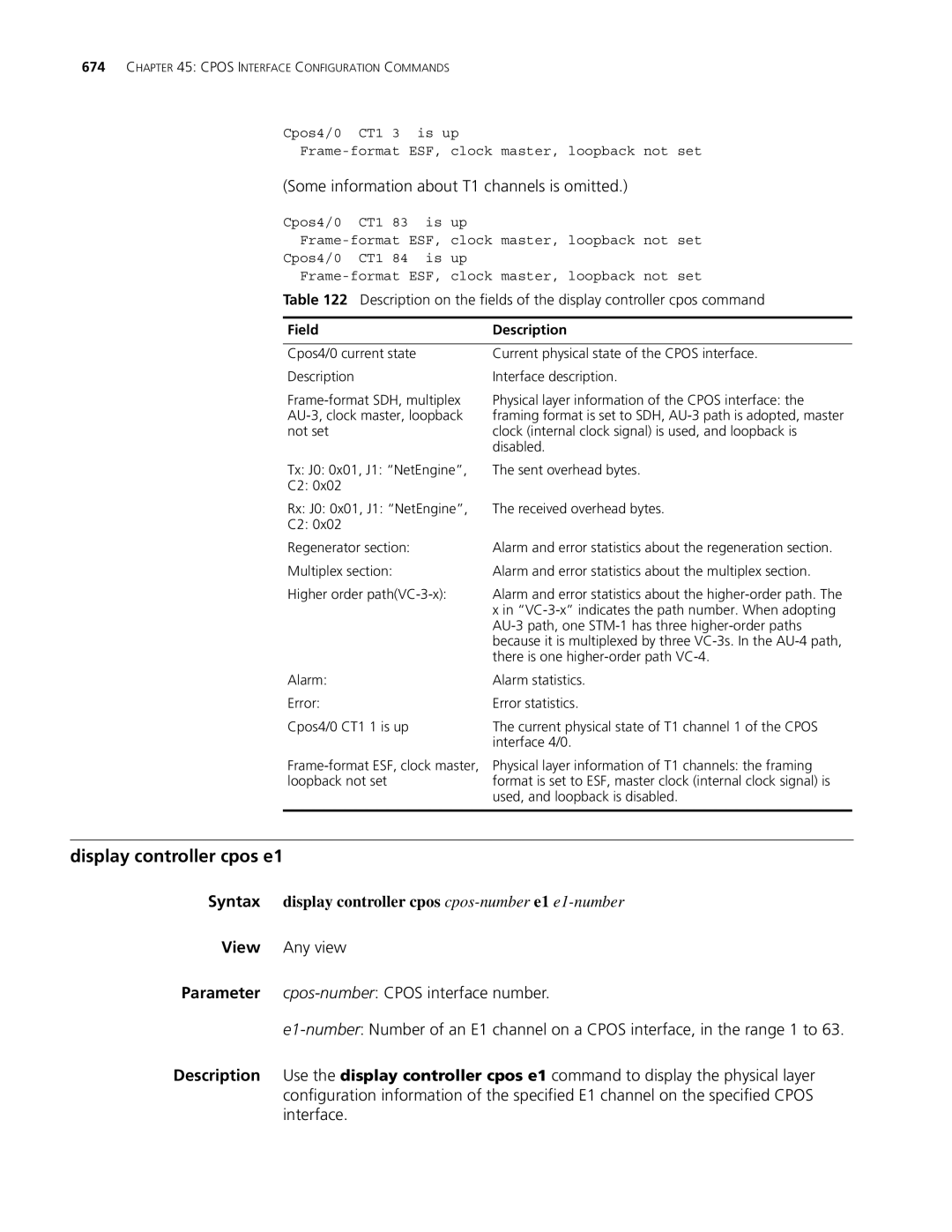
673
This table, FRED, COFA, and SEF are alarm errors AERRs
Possible error types
Syntax display controller cpos cpos-numbere1 e1-number
Display controller cpos e1
Some information about T1 channels is omitted
675
Display controller cpos t1
Syntax display controller cpos cpos-numbert1 t1-number
VC-3
Example # Bundle timeslots on E1 channel
677
E1 set clock
679
Related command display controller cpos e1
Example # Enable external payload loopback on E1 channel
Syntax e1 e1-numbershutdown undo e1 e1-numbershutdown
Syntax e1 e1-numberunframed undo e1 e1-numberunframed
Syntax frame-format sdh sonet undo frame-format
Undo flag j0 j1 c2
Display controller cpos
# Enable external loopback on interface Cpos 1/0
Multiplex mode
Use the undo loopback command to remove a loopback
Syntax multiplex mode au-3 au-4 undo multiplex mode
683
Related command frame-format
Example # In SDH mode, multiplex AUG to AU-3
Example # Shut down Cpos physical interface 1/0
Example # Bundle timeslots on T1 channel
685
Syntax t1 t1-numbershutdown Undo t1 t1-numbershutdown
Related command display controller cpos t1
Example # Enable external loopback on T1 channel
Syntax t1 t1-numberunframed Undo t1 t1-numberunframed
687
Cpos Interface Configuration Commands
Syntax arp check enable Undo arp check enable
ARP Configuration Commands
Arp check enable
Arp max-learning-num
Arp static
Related command display arp timer aging
Arp timer aging
Related command reset arp, display arp
Display arp
# Display the number of all ARP entries
Related command arp static, reset arp
Description on the fields of the display arp command
Display arp timer aging
Display arp timer aging
Arp static , and reset arp Example
Arp timer aging
Syntax naturemask-arp enable Undo naturemask-arp enable
Naturemask-arp enable
Related command arp static and reset arp
Display arp vpn-instance
Arp static and display arp
Reset arp
Specified by the argument interface-type interface-number
ARP Configuration Commands
Gratuitous-arp-learning enable
Gratuitous ARP Configuration Commands
Gratuitous-arp-sending enable
Gratuitous-arp-sending enable
Sysname system-view Sysname gratuitous-arp-learning enable
Arp source-suppression limit
ARP Source Suppression Configuration Commands
Arp source-suppression enable
Display arp source-suppression
Syntax display arp source-suppression
Related command display arp source-suppression
Display arp source-suppression
Description on fields of display arp source-suppression
Syntax arp authorized enable Undo arp authorized enable
Authorized ARP Configuration Commands
Arp authorized enable
Arp authorized time-out
Authorized ARP Configuration Commands
Local-proxy-arp enable
Proxy ARP Configuration Commands
Proxy-arp enable
Related command display proxy-arp
Local-proxy-arp enable
Related command display local-proxy-arp
Proxy-arp enable
Display proxy-arp
Dhcp Server Configuration Commands
Syntax bootfile-name bootfile-name Undo bootfile-name
Bootfile-name
Dhcp enable
Syntax dhcp enable Undo dhcp enable
Syntax dhcp server detect Undo dhcp server detect
Dhcp select server global-pool
Dhcp server detect
707
Dhcp server forbidden-ip
Dhcp server ip-pool
Dhcp server ping packets
Dhcp server ping timeout
Related command dhcp enable
Example # Create the Dhcp address pool identified by
Syntax dhcp update arp Undo dhcp update arp
Dhcp server relay information enable
Dhcp update arp
Display dhcp server expired
Reset dhcp server conflict
Display dhcp server conflict
Display dhcp server conflict all ip ip-address
Display dhcp server free-ip
Display dhcp server free-ip
Display dhcp server forbidden-ip
Syntax display dhcp server forbidden-ip
Binding information of all address pools is displayed
Reset dhcp server ip-in-use
Display dhcp server ip-in-use
Information of Dhcp address pools or an IP address
Syntax display dhcp server statistics
Reset dhcp server statistics
Display dhcp server statistics
Example # Display the statistics on the Dhcp server
Information of Dhcp address pools
Display dhcp server tree
Display dhcp server tree all pool pool-name
715
Dns-list
Undo dns-list ip-addressall
Expired
Related command dhcp server ip-pool
Domain-name
Gateway-list
Nbns-list
Netbios-type
Related command dhcp server ip-pooland netbios-type
719
Undo network
Related command dhcp server ip-pooland nbns-list
Network
721
Option
Undo option code
Reset dhcp server statistics
Reset dhcp server conflict
Reset dhcp server ip-in-use
Example # Clear the statistics of the Dhcp server
Related command display dhcp server statistics
Static-bind client-identifier
723
Static-bind ip-address
725
Static-bind mac-address
Tftp-server domain-name
Tftp-server ip-address
Voice-config
Undo voice-config as-ip fail-over ncp-ip voice-vlan
View Dhcp address pool view
727
Dhcp Server Configuration Commands
Syntax dhcp relay address-check disable enable
Dhcp Relay Agent Configuration Commands
Dhcp Snooping cannot be configured on the Dhcp relay agent
Dhcp relay address-check
Dhcp relay information enable
Dhcp relay information format
Undo dhcp relay information strategy
Dhcp relay information strategy
Dhcp relay information strategy drop keep replace
Syntax dhcp relay release ip client-ip
Dhcp relay release ip
Dhcp relay security static
Undo dhcp relay security ip-address all dynamic static
733
Related command display dhcp relay security
Dhcp relay security tracker
Dhcp relay server-detect
Dhcp relay server-detect
Dhcp relay server-group
Undo dhcp relay server-detect
735
Related command display dhcp relay server-group
Dhcp relay server-select
Dhcp select relay
Dhcp update arp
Dhcp select relay
Undo dhcp select relay
Server group that a specified interface corresponds to
Display dhcp relay
Display dhcp relay security
Groups correlated to an interface or all interfaces
Display dhcp relay security statistics
Display dhcp relay security statistics
Display dhcp relay security tracker
Information about bindings of Dhcp relay agents
Interval is 10 seconds
Display dhcp relay server-group
Display dhcp relay statistics
Syntax display dhcp relay server-group group-idall
Server Client
Which to remove statistics from the relay agent
Reset dhcp relay statistics
Reset dhcp relay statistics server-group group-id
Display dhcp relay statistics
Dhcp Relay Agent Configuration Commands
Dhcp Client Configuration Commands
Description on fields of the display dhcp client command
Ip address dhcp-alloc
745
Dhcp Client Configuration Commands
Dhcp-snooping
Dhcp Snooping Configuration Commands
Related command display dhcp-snooping
Dhcp-snooping trust
Display dhcp-snooping trust
Related command display dhcp-snooping trust
Display dhcp-snooping
Dhcp-snooping
# Display information about trusted ports
Related command dhcp-snooping trust Example
Trusted ports
749
Dhcp Snooping Configuration Commands
Display information about Bootp clients on all interfaces
Bootp Client Configuration Commands
Bootp client
Including sub-interfaces and Vlan interfaces
Related command display bootp client
Ip address bootp-alloc
Syntax ip address bootp-alloc Undo ip address bootp-alloc
Description on fields of the display bootp client command
Undo debugging dhcp server all error event packet
Dhcp Debugging Commands
Debugging dhcp server all error event packet
Debugging dhcp server
DHCPmessagetype
Dhcp ACK Dhcp NAK
755
Checking for an expired lease
DHCP-DISCOVER packet received
Checking whether the IP address 22.0.0.2 is in use
DHCP-REQUEST message received
Debugging dhcp relay
Sending a DHCP-ACK message
Sysname Terminal debugging
759
Debugging dhcp client
Debugging dhcp client all error event packet
Undo debugging dhcp client all error event packet
Then broadcast it
761
State of the Dhcp client is changed from Halt to Init
763
Head
Dhcp client starts address conflict detection using ARP
ARP message sent
Display dns dynamic-host
DNS Configuration Commands
Display dns domain
Dns domain Example
TTL
Display dns proxy table
Syntax display dns proxy table
Display ip host
Related command dns server
Display dns server
Syntax display dns server dynamic
Syntax dns proxy enable Undo dns proxy enable
Dns proxy enable
Related command display dns domain
Dns domain
Syntax dns resolve Undo dns resolve
Dns resolve
Dns server
Syntax dns server ip-address Undo dns server ip-address
Related command display ip host
Reset dns dynamic-host
Related command display dns server
Syntax reset dns dynamic-host
Related command display dns dynamic-host
771
DNS Configuration Commands
Display ip count inbound-packets outbound-packets exterior
IP Accounting Configuration Commands
Display ip count
Firewall-denied interior
Description on fields of the display ip count rule command
Ip count enable
Syntax ip count enable Undo ip count enable
Display ip count rule
Ip count firewall-denied
Example # Enable IP accounting
Ip count exterior-threshold
775
Ip count inbound-packets
# Specify not to count incoming IP packets on Ethernet1/0
Ip count interior-threshold
Example # Count incoming IP packets on Ethernet1/0
777
Ip count outbound-packets
Ip count rule
Syntax ip count timeout minutes Undo ip count timeout
Ip count timeout
Reset ip count
Syntax reset ip count all exterior firewall interior
Interior Clears the statistics from the interior table
All Clears all statistics
Exterior Clears the statistics from the exterior table
# Clear the statistics of all IP packets
IP Addressing Configuration Commands
Display ip interface
Description on fields of the display ip interface command
Example # Display brief information about Ethernet 1/0
Related command display ip interface
Display ip interface brief
783
Displayed
Ip address unnumbered
785
IP Addressing Configuration Commands
IP Performance Configuration Commands
Display fib
# Display FIB information passing the IP prefix list abc0
Description on the fields of the display fib command
# Display FIB information passing ACL
For description about the above output, refer to Table
Display fib ip-address
Display fib statistics
Syntax display fib statistics
Example # Display Icmp statistics
Display icmp statistics
Syntax display icmp statistics
3072
Display ip socket
100
# Display all socket information
Syntax display ip statistics
Description on the fields of the display ip socket command
Display ip statistics
Syntax display tcp statistics
Display tcp statistics
Example # Display statistics of IP packets
793
Related command display tcp status and reset tcp statistics
Example # Display statistics of TCP traffic
795
Display udp statistics
Related command reset udp statistics
Display tcp status
Display tcp status
Undo ip forward-broadcast
Ip forward-broadcast
Ip forward-broadcast acl acl-number
Ip redirects enable
Ip ttl-expires enable
Reset tcp statistics
Ip unreachables enable
Reset ip statistics
Related command display tcp statistics
Reset udp statistics
Tcp anti-naptha enable
Syntax reset udp statistics
Tcp mss
Tcp state
This support for this command varies with devices
Tcp syn-cookie enable
Related command tcp anti-naptha enable
Syntax tcp syn-cookie enable Undo tcp syn-cookie enable
Example # Enable the SYN Cookie feature
Tcp timer check-state
Tcp timer fin-timeout
803
Related command tcp timer fin-timeoutand tcp window
Tcp timer syn-timeout
Related command tcp timer syn-timeoutand tcp window
805
Tcp window
Syntax tcp window window-size Undo tcp window
IP Performance Configuration Commands
Apply ip-address default next-hop
IP Unicast Policy Routing Configuration Commands
Apply default output-interface
View policy-based-route view
Undo apply ip-address next-hop ip-address ip-address
Parameters ip-address IP address of the default next hop
Apply ip-address next-hop
IP precedences and the corresponding keywords
Apply ip-precedence
Examples # Set the next hop to 1.1.1.1 for matched packets
809
Syntax display ip policy-based-route
Apply output-interface
Display ip policy-based-route
Display ip policy-based-route setup
811
Interface-number
Local Displays statistics of enabled system policy routing
Display ip policy-based-route statistics
Routing statistics
If-match acl
Related commands if-matchpacket-length
Display policy-based-route
Syntax display policy-based-route policy-name
Ip local policy-based-route
Related commands if-match acl
If-match packet-length
Ip policy-based-route
Related commands policy-based-route
Related commands ip local policy-based-route
Policy-based-route
Syntax reset policy-based-route statistics policy-name
Reset policy-based-route statistics
Related commands if-match acl and if-matchpacket-length
817
IP Unicast Policy Routing Configuration Commands
Reset udp-helper packet
UDP Helper Configuration Commands
Reset udp-helper packet
Display udp-helper server
Udp-helper port
Udp-helper enable
Syntax udp-helper enable Undo udp-helper enable
821
Related command display udp-helper server
Udp-helper server
UDP Helper Configuration Commands
Ip urpf
Urpf Configuration Commands
Ip urpf loose strict allow-default-route acl acl-number
Undo ip urpf
Urpf Configuration Commands
Ip fast-forwarding
Fast Forwarding Commands
Display ip fast-forwarding cache
Display ip fast-forwarding cache
Fast Forwarding Commands
827
Reset ip fast-forwarding cache
Syntax reset ip fast-forwarding cache
Fast Forwarding Commands
Display dns ipv6 server
IPV6 Basics Configuration Commands
Display dns ipv6 dynamic-host
Syntax display dns ipv6 dynamic-host
Syntax display ipv6 fib ipv6-address
Display ipv6 fib
Example # Display IPv6 DNS server information
Display ipv6 host
Description on fields of the display ipv6 fib command
Display ipv6 fibcache
Syntax display ipv6 fibcache
Display ipv6 interface
Shutdown command
833
Display ipv6 neighbors
Display ipv6 neighbors count
Static vlan vlan-id count
Display ipv6 socket
Description on fields of the display ipv6 pathmtu command
Display ipv6 pathmtu
Syntax display ipv6 pathmtu ipv6-addressall dynamic static
Syntax display ipv6 statistics
Description on fields of the display ipv6 socket command
Display ipv6 statistics
837
Description on fields of the display ipv6 statistics command
839
Statistics
Display tcp ipv6 statistics
Display tcp ipv6 statistics
# Display the statistics of IPv6 TCP connections
841
Display tcp ipv6 status
Syntax display tcp ipv6 status
843
Display udp ipv6 statistics
Syntax display udp ipv6 statistics
TCP6CB
Syntax ipv6
Dns server ipv6
Ipv6
Undo ipv6
845
Ipv6 address
Ipv6 address auto link-local
Ipv6 address eui-64
Ipv6 address link-local
Syntax ipv6 fibcache Undo ipv6 fibcache
Ipv6 fibcache
Ipv6 fib-loadbalance-type hash-based
847
Ipv6 icmp-error
Ipv6 host
Syntax ipv6 mtu mtu-size Undo ipv6 mtu
Ipv6 icmpv6 multicast-echo-reply enable
Ipv6 mtu
849
Ipv6 nd autoconfig managed-address-flag
Ipv6 nd autoconfig managed-address-flag
Ipv6 nd autoconfig other-flag
Undo ipv6 nd autoconfig managed-address-flag
Syntax ipv6 nd dad attempts value Undo ipv6 nd dad attempts
Ipv6 nd dad attempts
Ipv6 nd hop-limit
Syntax ipv6 nd hop-limit value Undo ipv6 nd hop-limit
Ipv6 nd ns retrans-timer
Ipv6 nd nud reachable-time
On a router # Suppress RA messages on Ethernet1/0
Ipv6 nd ra halt
Syntax ipv6 nd ra halt Undo ipv6 nd ra halt
853
Undo ipv6 nd ra interval
Ipv6 nd ra interval
Ipv6 nd ra prefix
Undo ipv6 nd ra prefix ipv6-prefix
Ipv6 nd ra router-lifetime
855
Ipv6 neighbor
Undo ipv6 pathmtu ipv6-address
Ipv6 neighbors max-learning-num
Ipv6 pathmtu
857
Syntax reset dns ipv6 dynamic-host
Reset dns ipv6 dynamic-host
Related command display ipv6 pathmtu
Ipv6 pathmtu age
Reset ipv6 pathmtu
Reset ipv6 fibcache
Reset ipv6 neighbors
Reset udp ipv6 statistics
Reset ipv6 statistics
Reset tcp ipv6 statistics
ICMPv6 packets
Example # Clear the statistics of all UDP packets
Tcp ipv6 timer fin-timeout
Tcp ipv6 timer syn-timeout
861
Tcp ipv6 window
Syntax tcp ipv6 window size Undo tcp ipv6 window
Display natpt address-mapping
NAT-PT Configuration Commands
Display natpt address-group
Display natpt address-group
Display natpt aging-time
Syntax display natpt aging-time
Display natpt all
Example # Display all NAT-PT configuration information
Display natpt all
865
Display natpt frag-sessions
Syntax display natpt frag-sessions
Syntax display natpt session all icmp tcp udp
Display natpt session
Display natpt statistics
Display natpt statistics
Natpt address-group
Undo natpt address-group group-number
Natpt aging-time
Natpt max-session
Natpt enable
Syntax natpt enable Undo natpt enable
Syntax natpt max-session max-number Undo natpt max-session
Undo natpt prefix natpt-prefix
Example # Configure a NAT-PT prefix
Natpt prefix
871
Natpt turn-off tos
Natpt turn-off tos
Natpt turn-off traffic-class
Undo natpt turn-off tos
873
Natpt v4bound dynamic
Natpt v4bound static
Natpt v6bound dynamic
Natpt v6bound static
Reset natpt dynamic-mappings
Syntax reset natpt dynamic-mappings
Undo natpt v6bound static ipv6-addressipv4-address
# Clear all NAT-PT statistics information
Reset natpt statistics
Reset natpt statistics
Dual Stack Configuration Commands
Automatically created link-local address
Ipv6 address auto link-local
Automatically create a link-local address for an interface
Ethernet interface view
Example # Configure a link-local address on Ethernet 1/1
879
Dual Stack Configuration Commands
Destination
Tunneling Configuration Commands
Related command interface tunnel and source
Undo destination
Example # Display information of the interface tunnel
Display interface tunnel
Syntax display interface tunnel number
883
Display ipv6 interface tunnel
Syntax display ipv6 interface tunnel number
Syntax encapsulation-limit number Undo encapsulation-limit
Encapsulation-limit
Interface tunnel
Syntax interface tunnel number
885
Undo interface tunnel number
Example # Create the interface tunnel
Undo source
Related command interface tunnel and destination
Source
Undo tunnel-protocol
Tunnel-protocol
Ipv4-ipv6
Tunneling Configuration Commands
View IPv6 policy-based-route view
IPV6 Unicast Policy Routing Configuration Commands
Apply destination-based-forwarding
Apply ipv6-address default next-hop
Example # Set a next hop of 11 for matched IPv6 packets
Apply ipv6-address next-hop
Apply ipv6-precedence
Preferences and the corresponding keywords
Apply output-interface
Display ipv6 policy-based-route
Display ipv6 config policy-based-route
Syntax display ipv6 config policy-based-route policy-name
Display ipv6 policy-based-route
Display ipv6 policy-based-route setup
Local Displays system policy routing information
If-match acl6
Related command if-matchpacket-length
Display ipv6 policy-based-route statistics
Syntax if-match acl6 acl6-number Undo if-match acl6
Example # Permit the packets matching ACL
Related command if-match acl6
Ipv6 local policy-based-route
Ipv6 policy-based-route system view
Related command ipv6 local policy-based-route
Ipv6 policy-based-route interface view
897
IPV6 Unicast Policy Routing Configuration Commands
Auto-link
Terminal Access Configuration Commands
Auto-close
Syntax auto-close time Undo auto-close
Bind vpn-instance
Syntax bind vpn-instance vpn-name Undo bind vpn-instance
View Terminal template view
Data protect router-unix
Data read block
Syntax data read block Undo data read block
Display rta
Data send delay
Syntax data send delay milliseconds Undo data send delay
# Display brief information about TTY
903
TTY
# Display statistics about terminal
# Display all the information about terminal access
Description on the fields of the display rta all command
905
Driverbuf size
# Display terminal access statistics
Driverbuf save
Syntax driverbuf save Undo driverbuf save
Undo driverbuf size
Idle-timeout
Syntax idle-timeout seconds Undo idle-timeout
907
Menu screencode
Related command print information and print menu
Menu hotkey
Syntax menu hotkey ascii-code&1-3 Undo menu hotkey
909
Print connection-info
Syntax print connection-info Undo print connection-info
Print information
Related command print information
Related command print connection-infoand print menu
Print menu
Print language chinese english
Print language
Redrawkey
Terminal template view
Reset rta statistics terminal-number
Reset rta connection
Reset rta statistics
Undo resetkey
Resetkey
Related command display rta
Rta bind
Rta rtc-server listen-port
Rta source-ip
Rta server enable
Syntax rta server enable Undo rta server enable
Syntax rta source-ip ip-address Undo rta source-ip
Hiding
Rta template
Rta terminal
TCP connections
917
Sendbuf bufsize
Syntax sendbuf bufsize size Undo sendbuf bufsize
Syntax sendbuf threshold value Undo sendbuf threshold
Sendbuf threshold
Tcp
# Set the TCP send buffer size to 512 bytes
# Disable TCP delay
Testkey
Undo testkey
Update changed-config
Update changed-config
Access
Values are used for the hotkeys of flow control
Undo vty vty-numberdescription
Vty description
Vty hotkey
921
Vty password
923
Vty rtc-client remote
Vty rtc-server remote
Undo vty vty-numberscreencode
Related command menu screencode
Vty screencode
Example # Set the screen code for VTY 1 to E!9Q
Vty telnet remote
Vty tty remote
925
Syntax vty-switch priority Undo vty-switch priority
Vty-switch priority
Vty-switch threshold
Syntax vty-switch threshold times
Undo vty-switch threshold
927
Terminal Access Configuration Commands
Display ip routing-table
IP Routing Table Commands
Bandwidth-based-sharing
Syntax bandwidth-based-sharing Undo bandwidth-based-sharing
Special characters for regular expressions
String, the end of a string
931
Display ip routing-table acl
Syntax display ip routing-table acl acl-number verbose
933
IP Routing Table Commands
Display ip routing-table ip-address
935
Display ip routing-table ip-addresslonger-match
Display ip routing-table ip-address
Display ip routing-table ip-address mask
Display ip routing-table ip-address mask longer-match
937
Display ip routing-table ip-prefix
939
Display ip routing-table protocol
For detailed description of the above output, see Table
View Any view
Display ip routing-table statistics
# Display summary information about static routes
Display ip relay-route vpn-instance vpn-instance-name
Display ip relay-route
Display ip relay-tunnel
# Display recursive route information
Examples # Display recursive tunnel information
Display load-sharing ip address
Display ipv6 routing-table
Syntax display ipv6 routing-table
943
Display ipv6 routing-table acl
Syntax display ipv6 routing-table acl acl6-number verbose
Display ipv6 routing-table ipv6-addressprefix-length
Display ipv6 routing-table ipv6-address
Refer to for description about the above output
Display ipv6 routing-table ipv6-address1 ipv6-address2
945
Display ipv6 routing-table ipv6-prefix
Display ipv6 routing-table protocol
# Display routing statistics
Display ipv6 routing-table statistics
Syntax display ipv6 routing-table statistics
947
Display ipv6 routing-table verbose
Display ipv6 routing-table verbose
Display ipv6 relay-route
Entire routing table and information for each route
# Display IPv6 recursive tunnel information
Display ipv6 relay-tunnel
Display ipv6 relay-tunnel
949
Syntax load-bandwidth bandwidth Undo load-bandwidth
Reset load-sharing
Load-bandwidth
Reset ipv6 routing-table statistics protocol all protocol
Reset ip routing-table statistics protocol
Reset ipv6 routing-table statistics
Ripng , or static
Sysname reset ipv6 routing-table statistics protocol all
Aggregate
BGP Configuration Commands
Configuration Commands on
Functions of the keywords
Syntax balance number Undo balance
If-match clause of the route-policy command
Balance BGP/BGP-VPN instance view
Suppress-policy
View BGP view/BGP-VPN instance view
Related commands display bgp routing-table
Bestroute as-path-neglect BGP/BGP-VPN instance view
955
Bestroute med-confederation BGP/BGP-VPN instance view
Comparison is not enabled by default
Bestroute compare-med BGP/BGP-VPN instance view
Syntax bestroute compare-med Undo bestroute compare-med
957
Bgp
Compare-different-as-med BGP/BGP-VPN instance view
Confederation id
Syntax confederation id as-number Undo confederation id
Confederation peer-as
Related commands confederation id and confederation peer-as
Confederation nonstandard
View BGP view
Examples # Specify confederation peer sub ASs 2000
Dampening BGP/BGP-VPN instance view
Undo confederation peer-as as-number-list
Undo dampening
Syntax default ipv4-unicast Undo default ipv4-unicast
Default ipv4-unicast
Examples # In BGP view, configure BGP route dampening
961
Syntax default med med-value Undo default med
Default local-preference BGP/BGP-VPN instance view
Default med BGP/BGP-VPN instance view
963
Default-route imported BGP/BGP-VPN instance view
Syntax default-route imported Undo default-route imported
Display bgp group
Related commands import-routeBGP/BGP-VPN instance view
Description on the fields of the display bgp group command
Syntax display bgp group group-name
Display bgp network
Advertised with the network command
Display bgp network
# Display routing information that has been advertised
Display bgp peer
Description on the fields of the display bgp paths command
Display bgp paths
MED
Description on the fields of the display bgp peer command
967
Description on the fields of the display bgp routing command
Display bgp routing-table
Display bgp routing-table as-path-acl
969
Display bgp routing-table cidr
Display bgp routing-table cidr
971
Display bgp routing-table community
Display bgp routing-table community-list
Dampened BGP routes
Display bgp routing-table dampened
Display bgp routing-table dampened
# Display dampened BGP routes
Display bgp routing-table different-origin-as
Related commands dampening BGP/BGP-VPN instance view
Display bgp routing-table dampening parameter
Display bgp routing-table dampening parameter
Display bgp routing-table flap-info
Longer-match
975
Related commands display bgp peer
Display bgp routing-table peer
Ebgp-interface-sensitive
Display bgp routing-table regular-expression
Display bgp routing-table statistic
Display bgp routing-table statistic
977
Filter-policy export BGP/BGP-VPN instance view
Undo ebgp-interface-sensitive
Filter-policy import BGP/BGP-VPN instance view
Syntax graceful-restart Undo graceful-restart
Graceful-restart timer restart
Graceful-restart BGP view
979
Undo graceful-restart timer wait-for-rib
Graceful-restart timer wait-for-rib
Graceful-restart timer wait-for-rib timer
Using this command can speed up route convergence
Import-route BGP/BGP-VPN instance view
981
Log-peer-change
Syntax log-peer-change Undo log-peer-change
Network BGP/BGP-VPN instance view
983
Peer advertise-community BGP/BGP-VPN instance view
Peer advertise-ext-community BGP/BGP-VPN instance view
985
Related commands display bgp routing-table peer
Peer allow-as-loop BGP/BGP-VPN instance view
Undo peer ip-address
Peer as-number BGP/BGP-VPN instance view
Peer as-path-acl BGP/BGP-VPN instance view
Peer capability-advertise conventional
987
Peer capability-advertise route-refresh
Peer connect-interface BGP/BGP-VPN instance view
Peer default-route-advertise BGP/BGP-VPN instance view
Undo peer group-nameip-address default-route-advertise
Undo peer group-name ip-address connect-interface
Peer description BGP/BGP-VPN instance view
Peer ebgp-max-hop BGP/BGP-VPN instance view
991
Peer fake-as BGP/BGP-VPN instance view
Peer enable BGP view
Syntax peer ip-addressenable Undo peer ip-addressenable
993
Related commands peer as-path-aclBGP/BGP-VPN instance view
Peer filter-policy BGP/BGP-VPN instance view
Peer group BGP/BGP-VPN instance view
995
Peer ignore BGP/BGP-VPN instance view
Peer ip-prefix
Peer keep-all-routes BGP/BGP-VPN instance view
Undo peer group-name ip-address next-hop-local
Peer log-change BGP/BGP-VPN instance view
Peer next-hop-local BGP/BGP-VPN instance view
View BGP view /BGP-VPN instance view
Peer password
Undo peer group-name ip-address preferred-value
# Perform the similar configuration on the peer
Peer preferred-value BGP/BGP-VPN instance view
999
Peer public-as-only BGP/BGP-VPN instance view
Undo peer group-name ip-address public-as-only
Peer reflect-client BGP/BGP-VPN instance view
1001
Peer route-limit BGP/BGP-VPN instance view
Peer route-policy BGP/BGP-VPN instance view
Peer route-update-interval BGP/BGP-VPN instance view
1003
Peer substitute-as BGP/BGP-VPN instance view
Undo peer group-nameip-address substitute-as
1005
Peer timer BGP/BGP-VPN instance view
Related commands timer BGP/BGP-VPN instance view
Undo preference
Preference BGP/BGP-VPN instance view
Reflect between-clients BGP view
Syntax reflect between-clients Undo reflect between-clients
Examples # Set the cluster ID to
Examples # Disable route reflection between clients
Reflector cluster-id BGP view
1007
As-number Resets BGP connections to peers in the AS
Reset bgp
All Resets all BGP connections
Refresh bgp
1009
Reset bgp dampening
Reset bgp flap-info
Router-id
Reset bgp ipv4 all
Syntax reset bgp ipv4 all
Syntax router-id router-id Undo router-id
1011
Summary automatic
Syntax summary automatic Undo summary automatic
Synchronization BGP view
Timer BGP/BGP-VPN instance view
Syntax timer keepalive keepalive hold holdtime Undo timer
Syntax synchronization Undo synchronization
Related commands peer timer BGP/BGP-VPN instance view
1013
BGP Configuration Commands
BGP Debugging Commands
Debugging bgp all
BGP configuration information
BGP received an Open message from the peer
1017
Debugging bgp detail
Syntax debugging bgp detail Undo debugging bgp detail
Debugging bgp event
Route was deleted from the instance
State has changed from Opensent to Openconfirm
BGP has received an Update message
Debugging bgp graceful-restart
1019
BGP GR Helper received an EOR message from peer
BGP neighbor 10.1.1.1 is performing GR
BGP peer relationship has been successfully established
1021
Description on the fields of the debugging bgp command
Debugging bgp
AFI/ Safi
Description on the fields of the debugging bgp open command
Information about the sent BGP Open message
WTR
Information about the received BGP Keepalive message
Information about the received BGP Open message
Information about the sent BGP Keepalive message
1023
Debugging bgp timer
ConnectRetry timer for BGP peer 2.2.2.2 expired
Send Enables the debugging for sent BGP packets
Hold timer expired on BGP peer
Receive Enables the debugging for received BGP packets
Update messages
Ip-prefix ip-prefix-name receive send verbose
Debugging bgp update ipv4
Ip-prefix-name receive send verbose
1027
Debugging bgp update ipv6
Update messages of IPv4 address family
For IPv6 BGP update messages
Receive Enables/disables debugging for received BGP packets
Send Enables/disables debugging for sent BGP packets
Complete By default, this debugging is disabled
Verbose
Debugging bgp update l2vpn
Update messages of IPv6 address family
Send verbose
Acl-number ip-prefix ip-prefix-name receive send verbose
Debugging bgp update label-route
Update messages in an L2VPN environment
Receive send verbose
Update message information of L3VPN labeled routes
1031
Debugging bgp update peer
Update message information of IPv6 labeled routes
For BGP Vpls Update messages
Debugging bgp update vpls
Vpls Update messages
1033
Information about the received Vpls update message
Debugging bgp update vpn-instance
Information about the sent Vpls update message
For BGP VPNv4 Update messages
Debugging bgp update vpnv4
BGP VPNv4 Update messages
Examples None
Update message information of VPNv4
Area-authentication-mode simple md5 password ip osi
IS-IS Configuration Commands
Area-authentication-mode
Undo area-authentication-mode
Related commands bandwidth-referenceIS-IS view, cost-style
Auto cost enable
Syntax auto-cost enable Undo auto-cost enable
Bandwidth-reference IS-IS view
1039
Related commands auto cost enable
Circuit-cost
Relax-spf-limit
Related commands isis cost, cost-style
Cost-style
Undo cost-style
1041
Default-route-advertise IS-IS view
Related commands isis cost
Description on the fields of the display isis brief command
Display isis brief
Display isis debug-switches
Display isis graceful-restart status
Verbose Displays IS-IS interface detail information
Display isis interface
Traffic-eng Displays IS-IS traffic engineering information
Tunnel Displays IS-IS tunnel information
1045
Examples # Display IS-IS enabled interface information
# Display detailed IS-IS interface information
DIS
BFD
Display isis license
Syntax display isis license
Display isis lsdb
License information varies with device models
ATT/P/OL
Display isis mesh-group
Lspid
Display isis name-table
# Display the configuration information of IS-IS mesh-group
# Configure a static mapping for the remote IS-IS system
Display isis peer
# Display detailed IS-IS neighbor information
Display isis route
Up state and direct interface’s IP address
PRI
1051
Description on the fields of the display isis route command
# Display IS-IS IPv4 routing information
Display isis spf-log
Display isis statistics
Md5 Specifies to send the password encrypted with MD5
Domain-authentication-mode
Simple Specifies to send the password in plain text
IS-IS view
Filter-policy export IS-IS view
1055
Related commands filter-policy import IS-IS view
Filter-policy import IS-IS view
Level-1 level-2
Related commands filter-policy export IS-IS view
Flash-flood
Undo flash-flood level-1 level-2
Graceful-restart
Graceful-restart IS-IS view
Graceful-restart interval IS-IS view
Graceful-restart suppress-sa
Graceful-restart suppress-sa
Import-route IS-IS view
Undo graceful-restart suppress-sa
Related commands import-route isis level-2 into level-1
Examples # Redistribute static routes and set the cost to
Related commands import-routeIS-IS view
Import-route isis level-2 into level-1
Undo import-route isis level-2 into level-1
Isis authentication-mode
Isis
Undo isis circuit-level
This command is not available in loopback interface view
Isis circuit-level level-1 level-1-2 level-2
1063
Syntax isis circuit-type p2p Undo isis circuit-type
Related commands is-level
Isis circuit-type
Isis dis-name
Syntax isis dis-name symbolic-name Undo isis dis-name
Isis cost
1065
Examples # Configure the name as Localarea for the local LAN
Isis dis-priority
Related commands isis, network-entity
Isis enable
Syntax isis enable process-id Undo isis enable
Isis mesh-group
Isis peer-ip-ignore
Syntax isis peer-ip-ignore Undo isis peer-ip-ignore
Syntax isis small-hello Undo isis small-hello
Isis small-hello
Syntax isis silent Undo isis silent
1069
Isis timer csnp
Isis timer hello
Undo isis timer holding-multiplier level-1 level-2
Isis timer holding-multiplier
Isis timer holding-multiplier value level-1 level-2
Syntax isis timer lsp time count count Undo isis timer lsp
Isis timer lsp
Related commands isis timer hello
Related commands isis timer retransmit
Is-level
Isis timer retransmit
Related commands Examples Isis timer lsp
Syntax is-level level-1 level-1-2 level-2 Undo is-level
Is-name
Related commands isis circuit-level
Examples # Configure the router to work in Level-1
Syntax is-name sys-name Undo is-name
Is-name map
Is-snmp-traps enable
Syntax is-snmp-traps enable Undo is-snmp-traps
Undo is-name map sys-id
Log-peer-change IS-IS view
Lsp-fragments-extend
Lsp-length originate
1077
Maximum load-balancing IS-IS view
# Restore the default
Lsp-length receive
Syntax lsp-length receive size Undo lsp-length receive
Preference IS-IS view
Related commands Isis, isis enable Examples
Network-entity
Network-entity net
Reset isis all
Examples # Clear all IS-IS data structure information
Allow interlevel external
Reset isis peer
Set-overload
Undo set-overload
Spf-slice-size
Syntax spf-slice-size duration-time Undo spf-slice-size
Summary IS-IS view
1083
Generation interval
Timer isp-generation
Undo timer lsp-generation level-1 level-2
Interval
Syntax timer lsp-max-age seconds Undo timer lsp-max-age
Timer lsp-max-age
Timer lsp-refresh
Related commands timer lsp-refresh
Undo timer spf
Timer spf
Related commands timer lsp-max-age
Examples # Set the LSP refresh interval to 1500 seconds
Undo virtual-system virtual-system-id
Virtual-system
# Set the maximum SPF calculation interval to 15 seconds
1087
IS-IS Configuration Commands
Debugging isis
IS-IS Debugging Commands
Event Enables IS-IS event debugging
Ha-events interface-information memory-allocating
IS-IS Debugging Commands
1091
Snpa Snpa
Field
CircuitName not enabled
1093
SNP packet length mismatch
1095
Length length
Updt Reset Required
1097
Sending pduLevel pduType on circuitName
Sending pduLevel Csnp PDU fails
1099
Tent New Distance from RootNodeSourceId
1101
LSP
LevelType LSP level, which can be L1 or L2
1103
IP address took effect on the IS-IS interface
Router B sent Csnp packets
1105
IS-IS Debugging Commands
L3VPN Configuration Commands on
Ospf Configuration Commands
Related commands
Abr-summary Ospf area view
Syntax area area-id
Area Ospf view
Asbr-summary
Undo area area-id
Display ospf asbr-summary
Authentication-mode
Simple Specifies the simple authentication mode
View Ospf area view
Syntax default cost cost limit limit tag tag type type
Default
Related commands ospf authentication-mode
Bandwidth-reference Ospf view
Related commands import-route Ospf view
Default-cost Ospf area view
Undo default cost limit tag type
Syntax default-cost cost Undo default-cost
Default-route-advertise summary cost cost
Default-route-advertise Ospf view
Related commands stub Ospf area view, nssa
Undo default-route-advertise
Syntax description description Undo description
Description OSPF/OSPF area view
Display ospf abr-asbr
# Describe the Ospf area0 as bone area
Display ospf asbr-summary
Syntax display ospf process-id brief
Related commands asbr-summary
Display ospf brief
Examples # Display Ospf brief information
Description on the fields of the display ospf brief command
Mpls TE
1117
Display ospf cumulative
Syntax display ospf process-id cumulative
Nssa
Display ospf error
Syntax display ospf process-id error
ASE/NSSA
Description on the fields of the display ospf error command
1119
Display ospf interface
BDR
Display ospf lsdb
1121
Description on the fields of the display ospf lsdb command
# Display Type2 LSA Network LSA information in the Lsdb
1123
Display ospf nexthop
Syntax display ospf process-id nexthop
LS ID
Display ospf peer
# Display brief Ospf neighbor information
Description on the fields of the display ospf peer command
Display ospf peer statistics
Syntax display ospf process-id peer statistics
Display ospf request-queue
Keep neighbor relationship Init
1127
Display ospf retrans-queue
Examples # Display Ospf request list information
Display ospf routing
Syntax display ospf process-id vlink
Description on the fields of the display ospf vlink command
Display ospf vlink
1129
Error Enables error logging
Enable link-local-signaling
Enable log
State Enables state logging
1131
Enable out-of-band-resynchronization
Filter import/export
Filter-policy export Ospf view
By default, Summary LSAs filtering is disabled
This command is only available on an ABR
Undo filter-policy export protocol process-id
Graceful-restart Ospf view
Examples # Filter redistributed routes using ACL
Filter-policy import Ospf view
1133
Graceful-restart help
Examples # Enable Ietf Graceful Restart for Ospf process
# Enable non-IETF Graceful Restart for Ospf process
Syntax graceful-restart help acl-numberprefix prefix-list
Host-advertise
Related commands ospf timer dead
Graceful-restart interval Ospf view
1135
Import-route Ospf view
Import-route command cannot redistribute default routes
Related commands Examples
Default-route-advertise Ospf view
1137
Related commands lsa-generation-interval
Lsa-arrival-interval
Lsdb-overflow-limit
Related commands lsa-arrival-interval
Lsa-generation-interval
Undo lsa-generation-interval
Number Maximum route number in the range 1 to
Maximum load-balancing Ospf view
Maximum-routes
Nssa
Related commands ospf
Network Ospf area view
1141
Examples # Configure area1 as an Nssa area
Opaque-capability enable
Related commands default-cost Ospf area view
Syntax opaque-capability enable Undo opaque-capability
Undo ospf process-id
Ospf authentication-mode
Ospf
1143
Related commands authentication-mode
1145
Ospf cost
Syntax ospf cost value Undo ospf cost
Syntax ospf dr-priority priority Undo ospf dr-priority
Ospf dr-priority
Ospf mib-binding
Syntax ospf mib-binding process-id Undo ospf mib-binding
Ospf mtu-enable
Ospf network-type
This command is not supported on the Null interface
Ospf timer dead
Related commands ospf dr-priority
Syntax ospf timer dead seconds Undo ospf timer dead
Syntax ospf timer hello seconds Undo ospf timer hello
Ospf timer hello
Related commands ospf timer hello
1149
Syntax ospf timer poll seconds Undo ospf timer poll
Ospf timer poll
Ospf timer retransmit
Peer
Ospf trans-delay
Syntax ospf trans-delay seconds Undo ospf trans-delay
1151
Examples # Specify the neighbor IP address
Command sets priority for internal routes
Preference
Preference ase route-policy route-policy-name value
Syntax reset ospf process-id process
Reset ospf counters
Reset ospf process
1153
Rfc1583 compatible
Reset ospf redistribution
Syntax reset ospf process-id redistribution
Syntax rfc1583 compatible Undo rfc1583 compatible
Snmp-agent trap enable ospf
Silent-interface Ospf view
Ospf Configuration Commands
Undo spf-schedule-interval
Spf-schedule-interval
Stub Ospf area view
Syntax stub no-summary Undo stub
Stub-router
Default-cost Ospf area view
Stub-router
Undo stub-router
1159
Examples # Enable a stub-router
Vlink-peer Ospf area view
Related commands authentication-mode,display ospf peer
Syntax default cost value Undo default cost
RIP Configuration Commands
Default cost RIP view
Checkzero
# Disable default route sending
Default-route originate
Related commands import-route RIP view
Display rip
Description on the fields of the display rip command
1163
Syntax display rip process-iddatabase
Description on fields of the display rip database command
Display rip database
X.X/X
1165
Display rip interface
Display rip route
RIP Configuration Commands
# Display the routing statistics of RIP process
Description on the fields of the display rip route command
Filter-policy export RIP view
1167
Examples # Reference ACL 2000 to filter outbound routes
Filter-policy import RIP view
Interface-type interface-number Specifies an interface
1169
Host-route
Syntax host-route Undo host-route
Including bgp , direct , isis , ospf , rip , rip and static
Default cost RIP view
Import-route RIP view
1171
# Set the default cost for redistributed routes to
Maximum load-balancing RIP view
Syntax peer ip-address
Rip
Reset rip statistics
Syntax reset rip process-idstatistics
1173
Rip authentication-mode
Undo rip authentication-mode
# Enable Ethernet1/0 to receive RIP messages
Mode and parameters
By default, an interface is enabled to receive RIP messages
Format defined in RFC
Rip metricin
Related commands rip metricout
Related commands rip metricin
Rip metricout
Syntax rip mib-binding process-id Undo rip mib-binding
Rip mib-binding
Rip output
Syntax rip output Undo rip output
Rip split-horizon
Related commands rip input
Rip poison-reverse
Rip summary-address
Examples # Enable the split horizon function on Ethernet1/0
Related commands summary
Rip triggered
Rip version 1 2 broadcast multicast
Rip version
Undo rip triggered
Undo rip version
Messages
Silent-interface RIP view
All Silents all interfaces
1181
Summary
Timers
Related commands rip version
Syntax summary
Trip retransmit count
1183
Undo trip retransmit timer
Trip retransmit timer
Trip retransmit timer retransmit-time-value
Syntax validate-source-address Undo validate-source-address
Validate-source-address
Version
Version 1
Sysname system-view Sysname rip Sysname-rip-100 version
Apply comm-list delete
Routing Policy Common Configuration Commands
Apply as-path
Syntax apply comm-list comm-list-numberdelete
Apply community
Undo apply comm-list
View Routing policy view
Apply cost
Syntax apply cost + value Undo apply cost
Parameters + Increases cost value. + Decreases cost value
Apply cost-type
Apply extcommunity
Apply isis level-1 level-1-2 level-2 Undo apply isis
No level is set by default
Apply isis
1191
Apply mpls-label
Related commands route-policy
Apply local-preference
Syntax apply mpls-label Undo apply mpls-label
Syntax apply preference preference Undo apply preference
Apply origin
Apply preference
1193
Syntax apply tag value Undo apply tag
Apply preferred-value
Apply tag
Examples # Display the information of BGP AS path ACL
Display ip as-path
Syntax display ip as-path as-path-acl number
1195
Syntax display ip extcommunity-list ext-comm-list-number
Display ip community-list
Display ip extcommunity-list
Syntax display route-policy route-policy-name
Display route-policy
If-match as-path
Examples # Display the information of routing policy
If-match community
Related commands route-policy,ip as-pathacl
Related commands route-policyand ip community-list
Syntax if-match cost value Undo if-match cost
If-match cost
If-match extcommunity
1199
If-match interface
If-match mpls-label
If-match route-type
Syntax if-match tag value Undo if-match tag
If-match tag
Ip as-path
Undo ip as-path as-path-number
Ip community-list
1203
Sysname system-view Sysname ip community-list 100 permit
Undo ip extcommunity-list ext-comm-list-number
Ip extcommunity-list
Route-policy
1205
Routing Policy Common Configuration Commands
Syntax display ip ip-prefix ip-prefix-name
IPV4 Routing Policy Configuration Commands
Display ip ip-prefix
Related commands ip ip-prefix
Examples # Display the statistics of IPv4 prefix list abc
If-match ip-prefix
Related commands Route-policy Examples
If-match ip
Ip ip-prefix
1211
Reset ip ip-prefix
Syntax reset ip ip-prefix ip-prefix-name
IPV4 Routing Policy Configuration Commands
Display ip ipv6-prefix
IPV6 Routing Policy Configuration Commands
Apply ipv6 next-hop
Syntax display ip ipv6-prefix ipv6-prefix-name
String of 1 to 19 characters
If-match ipv6
Next-hop Matches the next hop of IPv6 routing information
Address based match criterion for IPv6 routes
Ip ipv6-prefix
1215
Examples # Clear the statistics of IPv6 prefix list abc
Reset ip ipv6-prefix
Syntax reset ip ipv6-prefix ipv6-prefix-name
Ip route-static
Static Routing Configuration Commands
Delete static-routes all
Examples # Delete all static routes on the router
Configured gateway-address
Associate it with a Track entry
Must be identical to that configured in the NQA test group
Ethernet interface and Vlan interface
1219
Ip route-static default-preference
Examples # Set the default preference of static routes to
Balance IPv6 address family view
IPV6 BGP Configuration Commands
Related commands display ipv6 routing-tableon
Bestroute as-path-neglect IPv6 address family view
Bestroute compare-med IPv6 address family view
Bestroute med-confederation IPv6 address family view
Compare-different-as-med IPv6 address family view
1223
Dampening IPv6 address family view
1225
Default local-preferenceIPv6 address family view
Default med IPv6 address family view
Syntax display bgp ipv6 group ipv6-group-name
Default-route imported IPv6 address family view
Display bgp ipv6 group
1227
Display bgp ipv6 network
Syntax display bgp ipv6 network
Display bgp ipv6 paths
Syntax display bgp ipv6 paths as-regular-expression
Incomplete
Display bgp ipv6 peer
1229
Display bgp ipv6 routing-table
Field Description Local router ID
Display bgp ipv6 routing-table as-path-acl
1231
Display bgp ipv6 routing-table community
Examples # Display routes filtered through the AS path ACL
Syntax display bgp ipv6 routing-table dampened
Display bgp ipv6 routing-table community-list
Display bgp ipv6 routing-table dampened
Examples # Display IPv6 BGP dampened routes
Syntax display bgp ipv6 routing-table dampening parameter
Display bgp ipv6 routing-table dampening parameter
Display bgp ipv6 routing-table different-origin-as
Syntax display bgp ipv6 routing-table different-origin-as
Examples # Display IPv6 BGP route flap statistics
Display bgp ipv6 routing-table flap-info
Examples # Display IPv6 BGP routes from different ASs
1235
Syntax display bgp ipv6 routing-table label
Command
Display bgp ipv6 routing-table label
Examples # Display IPv6 BGP label routing information
1237
Display bgp ipv6 routing-table peer
Display bgp ipv6 routing-table regular-expression
Parameters as-regular-expression AS regular expression
Display bgp ipv6 routing-table statistic
Filter-policy exportIPv6 address family view
Syntax display bgp ipv6 routing-table statistic
Filter-policy import IPv6 address family view
1239
Examples # Reference ACL6 2001 to filter all inbound routes
Group IPv6 address family view
Import-route IPv6 address family view
Syntax group ipv6-group-name internal external
Syntax ipv6-family Undo ipv6-family
Ipv6-family
Network IPv6 address family view
1241
Peer advertise-community IPv6 address family view
1243
Peer advertise-ext-community IPv6 address family view
Peer allow-as-loop IPv6 address family view
Peer as-number IPv6 address family view
1245
Peer as-path-acl IPv6 address family view
Import export
Peer connect-interface IPv6 address family view
1247
Peer default-route-advertise
Peer description IPv6 address family view
Peer ebgp-max-hop IPv6 address family view
1249
Peer enable IPv6 address family view
Peer fake-as IPv6 address family view
Peer filter-policy IPv6 address family view
1251
Peer group IPv6 address family view
Peer ignore IPv6 address family view
Peer ipv6-prefix
1253
Peer keep-all-routes IPv6 address family view
Peer label-route-capability IPv6 address family view
Peer log-change IPv6 address family view
Peer next-hop-local IPv6 address family view
Peer preferred-value IPv6 address family view
1255
Peer public-as-only IPv6 address family view
Peer reflect-client IPv6 address family view
Peer route-limit IPv6 address family view
1257
Peer route-update-interval IPv6 address family view
Peer route-policy IPv6 address family view
1259
Undo peer ipv6-group-nameipv6-address route-update-interval
Peer substitute-as IPv6 address family view
Preference IPv6 address family view
Peer timer IPv6 address family view
Related commands timer IPv6 address family view
Reflect between-clients IPv6 address family view
1261
Refresh bgp ipv6
Examples # Enable route reflection between clients
Reflector cluster-id IPv6 address family view
Reset bgp ipv6
1263
Reset bgp ipv6 dampening
Reset bgp ipv6 flap-info
Synchronization IPv6 address family view
1265
Timer IPv6 address family view
Related commands peer timer IPv6 address family view
1267
IPV6 BGP Configuration Commands
IPV6 IS-IS Configuration Commands
# Display detailed IPv6 IS-IS routing information
Ipv6 default-route-advertise
1271
Ipv6 filter-policy export
Ipv6 enable
Syntax ipv6 enable Undo ipv6 enable
Undo ipv6 filter-policy export protocol process-id
Undo ipv6 filter-policy import
Related commands ipv6 filter-policy import
Ipv6 filter-policy import
1273
Related commands ipv6 filter-policy export
Ipv6 import-route
1275
Ipv6 import-route isisv6 level-2 into level-1
Undo ipv6 import-route isisv6 level-2 into level-1
Ipv6 maximum load-balancing
Ipv6 preference
Ipv6 summary
1277
Syntax isis ipv6 enable process-id Undo isis ipv6 enable
Isis ipv6 enable
Examples # Configure a summary route of 2002/32
Area OSPFv3 view
IPV6 OSPFV3 Configuration Commands
Abr-summary OSPFv3 area view
Syntax default-cost value
Default cost
Default-cost OSPFv3 area view
Examples # Enter OSPFv3 Area 0 view
Display debugging ospfv3
Related commands stubOSPFv3 area view
Display debugging ospfv3
Debugging state information
Syntax display ospfv3 process-id
Description on the fields of the display isofv3 command
Display ospfv3
Display ospfv3 interface
1283
Display ospfv3 lsdb
# Display Link-local LSA information in the Lsdb
1285
Display ospfv3 lsdb statistic
Syntax display ospfv3 lsdb statistic
Syntax display ospfv3 process-id next-hop
Display ospfv3 next-hop
Display ospfv3 peer
Interface-type interface-number interface type and number
Description on the fields of the display isofv3 peer command
Syntax display ospfv3 peer statistic
Display ospfv3 peer statistic
Display ospfv3 request-list
Syntax display ospfv3 process-id request-list statistics
Syntax display ospfv3 process-id retrans-list statistics
Display ospfv3 retrans-list
# Display the statistics of OSPFv3 link state request list
LS-ID
Display ospfv3 routing
1291
# Display the statistics of OSPFv3 routing table
Syntax display ospfv3 statistic
Display ospfv3 statistic
Display ospfv3 topology
Syntax display ospfv3 process-id topology area area-id
Display ospfv3 vlink
Syntax display ospfv3 process-id vlink
Filter-policy exportOSPFv3 view
1295
Filter-policy importOSPFv3 view
Routes that fail to pass are not added to the routing table
Direct static
Import-routeOSPFv3 view
Allow-ibgp direct static cost value type type route-policy
Both Ebgp and Ibgp routes
Maximum load-balancingOSPFv3 view
Process
Ospfv3 area
Related commands router-id
Ospfv3
Undo ospfv3 process-id
Ospfv3 cost
Ospfv3 dr-priority
1301
Ospfv3 timer dead
Ospfv3 mtu-ignore
Ospfv3 timer hello
Related commands ospfv3 timer hello
Related commands ospfv3 timer dead
Ospfv3 timer retransmit
Ospfv3 trans-delay
1303
Preference ase route-policy route-policy-name preference
Router-id router-id
Related commands Ospfv3
Silent-interfaceOSPFv3 view
OSPFv3 processes on a router
Spf timers
Undo spf timers
Undo vlink-peer router-id hello retransmit trans-delay dead
Related commands default cost
Examples # Configure OSPFv3 area 1 as a stub area
StubOSPFv3 area view
IPV6 OSPFV3 Configuration Commands
Syntax default cost cost Undo default cost
IPV6 Ripng Configuration Commands
Default cost RIPng view
View RIPng view
Syntax display ripng process-id
Related commands import-route
Display ripng
Display ripng database
Description on the fields of the display ripng command
Description on fields of the display ripng database command
Syntax display ripng process-iddatabase
Display ripng interface
1313
Display ripng route
Syntax display ripng process-idroute
Filter-policy export
Filter-policy import RIPng view
Import-route
1315
Related commands default cost on
Maximum load-balancing RIPng view
Ripng
# Restore the default RIPng route priority
# Disable RIPng process
Undo ripng process-id
Syntax ripng process-idenable Undo ripng enable
Ripng default-route
Ripng enable
Ripng metricout
Related commands ripng metricout
Ripng metricin
Syntax ripng metricin value Undo ripng metricin
Ripng split-horizon
Related commands ripng metricin
Ripng poison-reverse
Syntax ripng poison-reverse Undo ripng poison-reverse
Ripng summary-address
Information, refer to Frame Relay Configuration Commands on
Lapb and X.25 Configuration Commands on
Poison reverse function takes effect
Timers
1323
IPV6 Ripng Configuration Commands
Ipv6 route-static
IPV6 Static Routing Configuration Commands
Delete ipv6 static-routes all
Delete ipv6 static-routes all
Sysname system-view Sysname ipv6 route-static 112 24
Display multicast boundary
Multicast Routing Forwarding Configuration Commands
Related command multicast boundary
Display multicast forwarding-table
MID
Major values of the flags field
1329
Value Meaning
Related command multicast minimum-ttl
Display multicast minimum-ttl
1331
Related command display multicast forwarding-table
Display multicast routing-table
Display multicast routing-table static
Description on the fields of display multicast routing-table
Display multicast rpf-info
1333
Ip rpf-route-static
1335
Related command display multicast routing-table static
Mtracert
1337
Description on the fields of the mtracert command
Multicast boundary
Related command display multicast boundary
Multicast forwarding-table downstream-limit
Multicast forwarding-table route-limit
1339
Syntax multicast longest-match Undo multicast longest-match
Multicast load-splitting
Multicast longest-match
View System view, VPN instance view
Multicast minimum-ttl
Multicast routing-enable
Related command display multicast minimum-ttl
1341
Reset multicast forwarding-table
# Enable IP multicast routing in VPN instance mvpn
Reset multicast routing-table
1343
Sysname reset multicast routing-table
Igmp Configuration Commands
Display igmp group
Description on the fields of the display igmp group command
Display igmp interface
1347
Display igmp routing-table
Igmp
Related command igmp fast-leave,last-member-query-interval
Fast-leave Igmp view
Syntax fast-leave group-policy acl-number Undo fast-leave
Syntax igmp enable Undo igmp enable
Igmp enable
Related command igmp enable, and multicast routing-enableon
Related command igmp
Undo igmp group-policy
Igmp fast-leave
Igmp group-policy
1351
Igmp max-response-time
By default, the last-member query interval is 1 second
Igmp last-member-query-interval
Igmp require-router-alert
1353
Igmp send-router-alert
Robust-count Igmp view , igmp timer query , igmp
Igmp robust-count
Igmp interface
Igmp static-group
Igmp timer other-querier-present
Igmp timer query
Last-member-query-interval
Related command version Igmp view
Igmp version
Undo igmp version
Syntax require-router-alert
Max-response-time Igmp view
Require-router-alert Igmp view
View Public instance Igmp view, VPN instance Igmp view
Reset igmp group
Undo require-router-alert
1359
Syntax robust-count robust-value Undo robust-count
Related command display igmp group
Robust-count Igmp view
Syntax send-router-alert Undo send-router-alert
Timer other-querier-present Igmp view
Send-router-alert Igmp view
1361
Public instance
Timer query Igmp view
Syntax timer query interval Undo timer query
1363
Related command igmp version
Version Igmp view
Igmp Configuration Commands
Display msdp brief
Msdp Configuration Commands
Cache-sa-enable
Characters
Display msdp peer-status
1367
Display msdp sa-cache
Related command cache-sa-enable
1369
Display msdp sa-count
Import-source
Encap-data-enable
Syntax encap-data-enable Undo encap-data-enable
View Public instance Msdp view, VPN instance Msdp view
Msdp
Related command peer sa-policy
Related command display multicast routing-tableon
Undo originating-rp
Originating-rp
Peer connect-interface
1373
Peer description
Related command static-rpf-peer
Related command display msdp peer-status
Peer mesh-group
Undo peer peer-addressminimum-ttl
Peer minimum-ttl
Undo peer peer-addressmesh-group
1375
Peer request-sa-enable
Peer sa-cache-maximum
From the Msdp peer
Import-source command
Peer sa-policy
Display msdp peer-status and import-source
Reset msdp peer
Peer sa-request-policy
1379
Reset msdp sa-cache
Related command cache-sa-enableand display msdp sa-cache
Undo shutdown peer-address
Reset msdp statistics
Shutdown Msdp View
Static-rpf-peer
Related command display msdp peer-statusand ip prefix-list
Example # Configure static RPF peers in the public instance
Undo static-rpf-peer peer-address
Timer retry
Syntax timer retry interval Undo timer retry
Related command static-rp PIM view
PIM Configuration Commands
Auto-rp enable
Bsr-policy PIM view
Bsr PIM view
Undo c-bsr
Bsr global
Bsr admin-scope
Syntax c-bsr admin-scope Undo c-bsr admin-scope
1385
Bsr group
Undo c-bsr group group-address
Syntax c-bsr hash-length hash-length Undo c-bsr hash-length
Bsr hash-length PIM view
Bsr holdtime PIM view
Syntax c-bsr holdtime interval Undo c-bsr holdtime
Bsr priority PIM view
Related command c-bsr PIM view and c-bsr interval PIM view
Bsr interval PIM view
Bsr PIM view and c-bsr holdtime PIM view
Rp PIM view
1389
Rp advertisement-interval interval
Related command c-bsr PIM view
Rp advertisement-interval PIM view
Undo c-rp advertisement-interval
Crp-policy PIM view
Related command c-rp PIM view and c-bsr interval PIM view
Rp holdtime PIM view
Syntax c-rp holdtime interval Undo c-rp holdtime
Related command c-bsr PIM view and c-rp PIM view
Display pim bsr-info
Display pim claimed-route
1393
Display pim control-message counters
1395
BSR
Display pim interface
Description on the fields of the display pim grafts command
Display pim grafts
1397
Display pim join-prune
PIM DR
Display pim neighbor
1399
Interface connecting the PIM neighbor
Display pim routing-table
1401
Sysname display pim routing-table Vpn-instance public net
Display pim rp-info
1403
Description on the fields of the display pim rp-info command
Hello-option holdtime PIM view
Related command pim hello-optiondr-priority
Hello-option dr-priority PIM view
1405
Related command pim hello-option holdtime
Hello-option lan-delay PIM view
This command is effective for both PIM-DM and PIM-SM
Hello-option neighbor-tracking PIM view
1407
Related command pim hello-optionneighbor-tracking
Hello-option override-interval PIM view
Syntax holdtime assert interval Undo holdtime assert
Holdtime assert PIM view
Holdtime join-prune PIM view
Jp-queue-size PIM view
Related command jp-queue-size PIM view
Jp-pkt-size PIM view
Syntax jp-pkt-size packet-size Undo jp-pkt-size
Undo pim vpn-instance vpn-instance-name
Related command multicast routing-enableon
Pim
Bsr PIM view , and multicast boundary on
Pim bsr-boundary
Pim dm
Related command hello-optiondr-priority PIM view
Related command pim sm, ssm-policy PIM view
Example # Enable PIM-DM on Ethernet 1/0
Pim hello-option dr-priority
Pim hello-option holdtime
Pim hello-option lan-delay
Related command hello-option holdtime PIM view
1413
Pim hello-option neighbor-tracking
Pim hello-option override-interval
1415
Pim holdtime assert
Pim holdtime join-prune
View Interface view Parameter None
Pim require-genid
Pim sm
Example # Enable PIM-SM on Ethernet 1/0
Pim timer graft-retry
Related command pim dm
Example # Disable state refresh on Ethernet 1/0
Syntax pim timer hello interval Undo pim timer hello
Pim timer hello
Pim timer join-prune
Related command timer hello PIM view
Probe-interval PIM view
Pim triggered-hello-delay
Related command timer join-prune PIM view
Syntax probe-interval interval Undo probe-interval
Syntax register-suppression-timeout interval
Register-suppression-timeout PIM view
Related command register-suppression-timeout PIM view
Register-policy PIM view
Syntax register-whole-checksum Undo register-whole-checksum
Undo register-suppression-timeout
Register-whole-checksum PIM view
1421
Source-lifetime PIM view
Reset pim control-message counters
Related command state-refresh-interval PIM view
Syntax source-lifetime interval Undo source-lifetime
Source-policy PIM view
Spt-switch-threshold PIM view
Undo spt-switch-threshold group-policy acl-number
Syntax source-policy acl-number Undo source-policy
PIM Configuration Commands
Syntax ssm-policy acl-number Undo ssm-policy
Ssm-policy PIM view
State-refresh-interval PIM view
1425
Syntax state-refresh-ttl ttl-value Undo state-refresh-ttl
State-refresh-rate-limit PIM view
State-refresh-ttl PIM view
Undo static-rp rp-address
By default, the TTL value of state refresh messages is
Static-rp PIM view
1427
Related command display pim rp-infoand auto-rp enable
Timer hello PIM view
Timer join-prune PIM view
Related command pim timer hello
Syntax timer spt-switch interval Undo timer spt-switch
Timer spt-switch PIM view
Related command pim timer join-prune
Related command spt-switch-threshold PIM view
PIM Configuration Commands
Display multicast ipv6 boundary
IPV6 Multicast Routing Forwarding Configuration Commands
Related command multicast ipv6 boundary
Display multicast ipv6 forwarding-table
IPV6 Multicast Routing and Forwarding Configuration Commands
1433
Display multicast ipv6 minimum-hoplimit
Values and meanings of the Flags field
Related command multicast ipv6 minimum-hoplimit
Display multicast ipv6 routing-table
1435
Related command display multicast ipv6 forwarding-table
Display multicast ipv6 rpf-info
Multicast ipv6 boundary
1437
Related command display multicast ipv6 boundary
Multicast ipv6 forwarding-table downstream-limit
Multicast ipv6 forwarding-table route-limit
Multicast ipv6 load-splitting
1439
Multicast ipv6 longest-match
Multicast ipv6 minimum-hoplimit
Multicast ipv6 routing-enable
Related command display multicast ipv6 minimum-hoplimit
1441
Reset multicast ipv6 forwarding-table
Reset multicast IPv6 routing-table
Sysname reset multicast ipv6 routing-table ff03101
MLD Configuration Commands
Display mld group
Information of all interfaces running MLD
Description on the fields of the display mld group command
Display mld interface
Display mld routing-table
1445
Fast-leave MLD view
Syntax fast-leave group-policy acl6-number Undo fast-leave
Syntax max-response-time interval Undo max-response-time
Last-listener-query-interval
Max-response-time MLD view
1447
Mld
Mld enable
Syntax mld enable Undo mld enable
Syntax mld
Mld fast-leave
Related command mld
Example # Enable MLD on Ethernet 1/0
Mld group-policy
Mld last-listener-query-interval
1451
Mld max-response-time
Mld require-router-alert
Mld robust-count
Syntax mld robust-count robust-value Undo mld robust-count
Mld send-router-alert
Mld send-router-alert
Mld static-group
Undo mld send-router-alert
Undo mld timer other-querier-present
Mld timer other-querier-present
Mld timer other-querier-present interval
125 x 2 + 10 / 2 = 255 seconds
Related command mld version
Mld timer query
Syntax mld timer query interval Undo mld timer query
Mld version
Require-router-alert
Reset mld group
Require-router-alert MLD view
Mld require-router-alert and send-router-alert MLD view
# Clear all MLD forwarding entries on Ethernet 1/0
Related command display mld group
Robust-count MLD view
1457
Send-router-alert MLD view
Timer other-querier-present MLD view
By default, the MLD querier robustness variable is
View MLD view
Timer query interval
Timer query MLD view
Related command
Version MLD view
Example # Globally set the MLD version to MLDv2
Bsr IPv6 PIM view
IPV6 PIM Configuration Commands
Bsr-policy IPv6 PIM view
Syntax bsr-policy acl6-number Undo bsr-policy
Related command c-bsr IPv6 PIM view on
Bsr hash-length IPv6 PIM view
Bsr interval IPv6 PIM view
Example # Set the bootstrap timeout time to 150 seconds
Bsr holdtime IPv6 PIM view
Syntax c-bsr interval interval Undo c-bsr interval
Rp IPv6 PIM view
Related command c-bsr IPv6 PIM view
Bsr priority IPv6 PIM view
Bsr IPv6 PIM view and c-bsr holdtime IPv6 PIM view
1465
Rp advertisement-interval IPv6 PIM view
View IPv6 PIM view
Rp holdtime IPv6 PIM view
Related command c-rp IPv6 PIM view
Example # Set the global C-RP timeout time to 200 seconds
Example # Set the global C-RP-Adv interval to 30 seconds
Display pim ipv6 bsr-info
Related command c-bsr IPv6 PIM view and c-rp IPv6 PIM view
Crp-policy IPv6 PIM view
Syntax crp-policy acl6-number Undo crp-policy
Display pim ipv6 claimed-route
Syntax display pim ipv6 claimed-route ipv6-source-address
Display pim ipv6 control-message counters
BSR
Display pim ipv6 grafts
Display pim ipv6 grafts
Display pim ipv6 interface
Unacknowledged graft messages
Interface PIM version PIM mode
To send on the specified interface
Display pim ipv6 join-prune
PIM-SM and IPv6 PIM-SSM respectively
Specified IPv6 PIM neighbor
Display pim ipv6 neighbor
Display pim ipv6 routing-table
1475
Related command display multicast ipv6 routing-tableon
Example # View the content of the IPv6 PIM routing table
1477
Display pim ipv6 rp-info
Syntax display pim ipv6 rp-info ipv6-group-address
Embedded-rp
Syntax embedded-rp acl6-number Undo embedded-rp acl6-number
Hello-option holdtime IPv6 PIM view
Related command pim ipv6 hello-optiondr-priority
Hello-option dr-priority IPv6 PIM view
Example # Set the router priority for DR election to
Example # Set the prune delay to 200 milliseconds globally
Hello-option lan-delay IPv6 PIM view
Related command pim ipv6 hello-option holdtime
Hello-option neighbor-tracking IPv6 PIM view
Hello-option override-interval IPv6 PIM view
Related command pim ipv6 hello-optionneighbor-tracking
Example # Disable join suppression globally
Holdtime assert IPv6 PIM view
Holdtime join-prune IPv6 PIM view
Jp-queue-size IPv6 PIM view
Related command jp-queue-size IPv6 PIM view
Jp-pkt-size IPv6 PIM view
1483
Pim ipv6 bsr-boundary
Related command multicast ipv6 routing-enableon
Pim ipv6
Syntax pim ipv6 Undo pim ipv6
Pim ipv6 dm
Related commands pim ipv6 sm, ssm-policy IPv6 PIM view
Example # Enable IPv6 PIM-DM on Ethernet 1/0
Syntax pim ipv6 dm Undo pim ipv6 dm
Pim ipv6 hello-option dr-priority
Related command hello-optiondr-priority IPv6 PIM view
Related command hello-option holdtime IPv6 PIM view
Pim ipv6 hello-option holdtime
1487
Pim ipv6 hello-option lan-delay
Pim ipv6 hello-option neighbor-tracking
Pim ipv6 hello-option override-interval
Related command hello-optionneighbor-tracking IPv6 PIM view
Example # Disable join suppression on Ethernet 1/0
Pim ipv6 holdtime assert
Syntax pim ipv6 require-genid Undo pim ipv6 require-genid
Pim ipv6 holdtime join-prune
Pim ipv6 require-genid
1489
Pim ipv6 sm
Pim ipv6 sm
Pim ipv6 state-refresh-capable
Undo pim ipv6 sm
1491
Pim ipv6 timer graft-retry
Pim ipv6 timer hello
Related command timer hello IPv6 PIM view
Pim ipv6 timer join-prune
Pim ipv6 triggered-hello-delay
Related command timer join-prune IPv6 PIM view
Register-policy IPv6 PIM view
Related command register-suppression-timeout IPv6 PIM view
Probe-interval IPv6 PIM view
Example # Set the probe time to 6 seconds
Register-suppression-timeout IPv6 PIM view
1495
Reset pim ipv6 control-message counters
Register-whole-checksum IPv6 PIM view
Source-policy IPv6 PIM view
Related command state-refresh-interval IPv6 PIM view
Source-lifetime IPv6 PIM view
Syntax source-policy acl6-number Undo source-policy
1497
Spt-switch-threshold IPv6 PIM view
Undo spt-switch-threshold group-policy acl6-number
Ssm-policy IPv6 PIM view
Syntax ssm-policy acl6-number Undo ssm-policy
1499
State-refresh-hoplimit
State-refresh-interval IPv6 PIM view
Example # Set the state refresh interval to 70 seconds
State-refresh-rate-limit IPv6 PIM view
Static-rp IPv6 PIM view
Undo static-rp ipv6-rp-address
Timer hello IPv6 PIM view
Related command display pim ipv6 rp-info
1501
Related command pim ipv6 timer hello
Timer join-prune IPv6 PIM view
Timer spt-switch IPv6 PIM view
Related command pim ipv6 timer join-prune
Related command spt-switch-threshold IPv6 PIM view
1503
IPV6 PIM Configuration Commands
Display multicast-domain vpn-instance share-group
Multicast VPN Configuration Commands
Display multicast-domain vpn-instance switch-group receive
Count
Display multicast-domain vpn-instance switch-group send
1507
Multicast-domain holddown-time
View VPN instance view
Multicast-domain log switch-group-reuse
Multicast-domain share-group
1509
Multicast-domain switch-delay
1511
Multicast-domain switch-group-pool
Undo multicast-domain switch-group-pool
Sysname system-view Sysname ip vpn-instance mvpn
Display mpls fast-forwarding cache verbose
Mpls Basics Configuration Commands
Display mpls fast-forwarding cache
# Display all ILM entries
Display mpls ilm
Syntax display mpls ilm label include text
1515
Related command display mpls statistics interface
Display mpls interface
Display mpls label
Display mpls label label-value1 to label-value2 all
Mpls ldp system view , mpls ldp interface view
Display mpls ldp
Display mpls ldp all verbose begin exclude include
LSR ID
Description on the fields of the display mpls ldp command
Display mpls ldp cr-lsp
All Displays all information
Related command display mpls lsp
Display mpls ldp interface
1519
Example # Display information about all LDP interfaces
# Display detailed information about all interfaces
Dest-addr Destination address of the LSP
Display mpls ldp Isp
All Displays information about all LSPs established by LDP
Established by LDP
Related command display mpls ldp
Display mpls ldp peer
1523
Example # Display information about all peers
# Display detailed information about all peers
Display mpls ldp remote-peer
Example # Display information about remote peer BJI
Display mpls ldp session
1525
LAM
Example # Display information about sessions
# Display detailed information about all sessions
MD5
Display mpls ldp vpn-instance
1527
Incoming-interface Incoming interface of the LSPs
Display mpls lsp
Example # Display information about VPN instance vpn1
Outgoing-interface Outgoing interface of the LSPs
Dest-addr Destination address
Exclude Excludes the specified FEC
Include Includes the specified FEC
Asbr Displays information about Asbr established LSPs
# Display detailed information about all LSPs
Description on the fields of the display mpls lsp command
Example # Display information about all LSPs
FEC
Syntax display mpls lsp statistics
Display mpls lsp statistics
Display mpls nhlfe
Syntax display mpls nhlfe token include text
Display mpls route-state
# Display all Nhlfe entries
Display mpls static-lsp
1533
# Display detailed information about static LSPs
Display mpls statistics interface
Example # Display brief information about static LSPs
1535
Related command statistics interval
Example # Display Mpls statistics for all interfaces
Display mpls statistics lsp
Syntax display mpls statistics lsp index all name lsp-name
Example # Display Mpls statistics for all LSPs
1537
Du-readvertise
Du-readvertise timer
Syntax du-readvertise timer value Undo du-readvertise timer
Are both
View Mpls LDP view
Graceful-restart Mpls LDP view
Graceful-restart mpls ldp
Syntax graceful-restart mpls ldp
Related commands graceful-restart Mpls LDP view
Graceful-restart timer neighbor-liveness
Graceful-restart timer reconnect
Syntax graceful-restart timer reconnect timer
1541
Graceful-restart timer recovery
Undo graceful-restart timer reconnect
Label advertise
Related command loop-detect,path-vectors
Hops-count
Syntax hops-count hop-number Undo hops-count
Label-distribution independent ordered
Label-distribution
Undo label advertise
Undo label-distribution
Undo label-retention
Label-retention
Label-retention conservative liberal
Loop-detect
Related command hops-count,path-vectors
Use the undo lsp-trigger command to restore the default
Lsp-trigger
Syntax lsr-idlsr-id
# Configure the LDP LSR ID of LDP instance named vpn1
Lsr-id
Undo lsr-id
Syntax mpls
Md5-password
Mpls
Undo mpls
Mpls ldp system view
Related command mpls lsr-id
# Enable Mpls for interface Ethernet 1/0
View System view/interface view
Syntax mpls ldp Undo mpls ldp
# Enable LDP for VPN instance vpn1
Mpls ldp interface view
1549
Undo mpls ldp advertisement
Mpls ldp advertisement
Mpls ldp advertisement dod du
Mpls ldp remote-peer
Mpls ldp timer hello-hold
Related command remote-ip
Example # Create a remote peer entity named BJI
Mpls ldp timer keepalive-hold
View Interface view/MPLS LDP remote peer view
Mpls ldp transport-address
Mpls lsr-id
Syntax mpls lsr-id lsr-id Undo mpls lsr-id
Syntax mtu-signalling Undo mtu-signalling
Mtu-signalling
Related command display mpls interface
Example # Set the LSR ID to
Ping lsp
Related command loop-detect,hops-count
Path-vectors
Syntax path-vectors pv-number Undo path-vectors
Remote-ip
Syntax remote-ip ip-address Undo remote-ip
Related command mpls ldp remote-peer
Reset mpls fast-forwarding cache
Reset mpls ldp
Reset mpls fast-forwarding cache
Syntax reset mpls statistics lsp index all name lsp-name
Reset mpls statistics interface
Reset mpls statistics lsp
Static-lsp egress
Snmp-agent trap enable mpls
Related command display mpls statistics lsp
Lsp-name Name for the LSP, a string of 1 to 15 characters
Static-lsp ingress
Undo static-lsp ingress lsp-name
1561
Static-lsp transit
Undo static-lsp transit lsp-name
Tracert lsp
Related command static-lsp egress, static-lsp ingress
Statistics interval
Syntax tracert lsp -a source-ip-exp
Ttl expiration pop
Ttl expiration pop command
Ttl expiration
Undo ttl expiration pop
Ttl propagate
Mpls TE Configuration Commands
Add hop
Syntax delete hop ip-address
Delete hop
Display explicit-path
Syntax display explicit-path pathname
1567
Display isis traffic-eng advertisements
# Display the latest TE information advertised by IS-IS TE
Intf Addr
1569
Display isis traffic-eng link
Verbose Displays details
Display isis traffic-eng network
Vpn-instance vpn-instance-name Specifies a VPN instance.
Display isis traffic-eng statistics
1571
Related command te-set-subtlv
Display isis traffic-eng sub-tlvs
Display mpls rsvp-te
Label switched Router ID,
About RSVP-TE globally or for an interface
Display mpls rsvp-te established
Begin include exclude regular-expression
# Display RSVP-TE information for interface Ethernet 1/0
Spaces
Display mpls rsvp-te peer
Filters output by regular expression
Display mpls rsvp-te psb-content
1577
Erhopstrict
1579
Display mpls rsvp-te request
RSVP-TE requests on the specified or all interfaces
X.X
Display mpls rsvp-te reservation
LSP ID
Display mpls rsvp-te rsb-content
1581
Tunnel Dest
Display mpls rsvp-te sender
1583
Interface is specified
Display mpls rsvp-te statistics
Global Display global RSVP-TE information
RSVP-TE is displayed
# Display the RSVP-TE statistics of interface Serial 1/0
1585
Display mpls static-cr-lsp
Ip-address prefix-length arguments
1587
Display mpls te cspf tedb
# Display detailed information about all static CR-LSPs
IGP
1589
# Display the Tedb information of IGP area
# Display all Tedb information
Mpls LSR ID IGP
# Display the Tedb information of all nodes
# Display Tedb information for a specified interface address
Display mpls te link-administration admission-control
Links of all interfaces if no interface is specified
1593
Display mpls te link-administration bandwidth-allocation
Description on fields of the command
Display mpls te tunnel
Egress ingress remote transit name name incoming-interface
LSP-ID
# Display detailed information about Mpls TE tunnels
1595
# Display the paths that all Mpls TE tunnels traverse
Display mpls te tunnel path
Lsr-id Ingress LSR ID, in dotted decimal notation
Syntax display mpls te tunnel statistics
Display mpls te tunnel statistics
Display mpls te tunnel-interface
Syntax display mpls te tunnel-interface
CR-LSP
Display ospf mpls-te
1599
Area ID TE enabled Ospf area ID LSA Type
1601
Display ospf traffic-adjustment
Syntax display ospf process-id traffic-adjustment
# Display statistics about tunnels
Display tunnel-info
Syntax display tunnel-info tunnel-id all statistics
# Enable IGP shortcut when the IGP protocol is IS-IS
Enable traffic-adjustment
Enable traffic-adjustment advertise
View Ospf view/IS-IS view
Explicit-path
List hop
1605
Modify hop
View Explicit path view
Undo mpls rsvp-te authentication
Mpls rsvp-te authentication
Mpls rsvp-te authentication cipher plain auth-key
Mpls rsvp-te
Mpls rsvp-te blockade-multiplier
1607
Mpls rsvp-te hello
Related command mpls rsvp-te timer refresh
Mpls rsvp-te graceful-restart
Syntax mpls rsvp-te hello Undo mpls rsvp-te hello
1609
# Enable Rsvp hello extension on interface Ethernet 1/0
Mpls rsvp-te hello-lost
Mpls rsvp-te reliability
Related command mpls rsvp-te timer hello
Mpls rsvp-te keep-multiplier
Example # Set the keep multiplier to five
Mpls rsvp-te resvconfirm
Mpls rsvp-te srefresh
Mpls rsvp-te timer graceful-restart recovery
Mpls rsvp-te timer graceful-restart restart
Related command mpls rsvp-te hello, mpls rsvp-tehello-lost
Mpls rsvp-te timer hello
Mpls rsvp-te timer refresh
Example # Set the hello interval to five seconds
Undo mpls rsvp-te timer retransmission
Mpls rsvp-te timer retransmission
Related command mpls rsvp-tekeep-multiplier
Syntax mpls te
# Enable Mpls TE on interface Ethernet 1/0
Mpls te
Undo mpls te
Mpls te auto-bandwidth
Related command mpls te link administrative group
Mpls te affinity property
Undo mpls te auto-bandwidth
Mpls te backup hot-standby ordinary
Mpls te backup
Related command mpls te timer auto-bandwidth
Undo mpls te backup
Example # Enable hot backup on tunnel
Mpls te backup bandwidth
With backup enabled, the record route
Mpls te bandwidth bc0 bc1 bandwidth
Mpls te bandwidth
Mpls te bandwidth change thresholds
Undo mpls te bandwidth
View Tunnel interface view
Mpls te commit
Syntax mpls te commit
Example # Set the failed link timer to 50 seconds
Mpls te cspf timer failed-link
Related command mpls te cspf
Mpls te cspf
Syntax mpls te fast-reroute Undo mpls te fast-reroute
Mpls te fast-reroute
Mpls te fast-reroute bypass-tunnel
# Set the hold time to 10000 milliseconds
Mpls te igp advertise
Description Example
1623
Mpls te igp shortcut isis ospf
Mpls te igp metric
Mpls te igp shortcut
Undo mpls te igp shortcut
Mpls te loop-detection
Mpls te link administrative group
Related command mpls te affinity property
Syntax mpls te loop-detection Undo mpls te loop-detection
Mpls te max-link-bandwidth
Mpls te max-reservable-bandwidth
Undo mpls te max-reservable-bandwidth
Related command mpls te path metric-type
Mpls te metric
Syntax mpls te metric value Undo mpls te metric
Mpls te path metric-type
Related command mpls te metric
Mpls te path explicit-path
Example In Mpls view
Undo mpls te priority
Mpls te priority
Mpls te record-route
Syntax mpls te record-route label Undo mpls te record-route
Mpls te reoptimization
Mpls te reoptimization user view
Mpls te reoptimization tunnel interface view
Mpls te resv-style
Mpls te retry
Example # Enable route pinning
Related command mpls te timer retry
Example # Set the maximum number of tunnel setup retries to
Mpls te route-pinning
Mpls te tie-breaking
Mpls te signal-protocol
Mpls te signal-protocol crldp rsvp-te static
Mpls te tie-breaking least-fill most-fill random
Related command mpls te auto-bandwidth
Mpls te timer auto-bandwidth
By default, automatic bandwidth adjustment is disabled
Syntax mpls te timer retry second Undo mpls te timer retry
Mpls te timer fast-reroute
Mpls te timer retry
1635
Mpls te tunnel-id
Related command mpls te retry
Examples # Configure the tunnel ID as
Mpls te vpn-binding
Related command opaque-capability
Mpls-te enable
Syntax mpls-te enable Undo mpls-te
Next hop
Related command delete hop
Opaque-capability
Syntax reset mpls te auto-bandwidth adjustment timers
Reset mpls rsvp-te statistics
Reset mpls te auto-bandwidth adjustment timers
Static-cr-lsp egress
Static-cr-lsp ingress
Undo static-cr-lsp transit tunnel-name
Static-cr-lsp transit
CR-LSP on the ingress or a transit node
Bw-constraint Sets the bandwidth constraint sub-TLV
Use the undo te-set-subtlvcommand to restore the default
# Configure sub-TLVs for IS-IS process
Value Sub-TLV in the range 19 to
If no level is specified, IS-IS TE applies to Level-1-2
Cost-style on
Mpls TE Configuration Commands
Mpls L2VPN Configuration
Ccc interface in-label out-label
Ccc interface out-interface
Undo ce ce-name
View Mpls L2VPN CE view
Connection
# Create a CE named ce2 for a VPN
1647
Tunnel select-seq load-balance-number on
Related command route-distinguisher Mpls L2VPN view
Display bgp l2vpn
1649
CE ID
Verbose Peer Local
1651
Pref Preference
# Display information about all local CCC connections
Display ccc
Syntax display ccc ccc-name ccc-nametype local remote
# Display information about all CCC connections
Display l2vpn ccc-interface vc-type
Down
Display mpls l2vc
Configured on the router
Configured on the CE interface
1655
VC ID
VC ID
Display mpls l2vpn
Vpn-name local-ce remote-ce
# Display information about local CEs of L2VPN vpn1
Description on the fields of the display mpls l2vpn command
# Display information about L2VPN vpn1
1659
Display mpls l2vpn connection
# Display information about remote CEs of L2VPN vpn1
Status Status of the connection Peer-id
Description on the fields of mpls l2vpn connection summary
Example # Display Mpls L2VPN forwarding information
Display mpls l2vpn forwarding-info
Display mpls static-l2vc
1663
L2vpn-family
Syntax l2vpn-family
Undo l2vpn-family
Related command tunnel select-seqload-balance-numberon
Mpls l2vc
Example # Create a Martini Mpls L2VPN connection
Mpls l2vpn
Mpls l2vpn vpn-name
Syntax mpls l2vpn Undo mpls l2vpn
Undo mpls static-l2vc
Mpls static-l2vc destination
# Create Kompella VPN named vpn2 and enter Mpls L2VPN view
Syntax mtu mtu
Reset bgp l2vpn
Mtu Mpls L2VPN view
Example # Set the MTU for Kompella connections to
Route-distinguisher Mpls L2VPN view
Re-create the VPN using the new RD
Takes effect only when it is configured with an RD
Route-distinguisher route-distinguisher
1669
Vpn-target Mpls L2VPN view
Example # Associate VPN vpn1 with VPN targets
Mpls L2VPN Configuration Commands
Syntax default local-preference value
Apply access-vpn vpn-instance
Default local-preference BGP-VPNv4 subaddress family view
View Policy routing view
Default med BGP-VPNv4 subaddress family view
1673
Description VPN instance view
Display bgp vpnv4 all routing-table
Example # Display all BGP VPNv4 routing information
1675
Display bgp vpnv4 group
All Specifies all VPNv4 peers
Display bgp vpnv4 network
Be displayed
Display bgp vpnv4 paths
Display bgp vpnv4 all vpn-instance vpn-instance-name paths
# Display all BGP VPNv4 AS path information
VPNv4 peers
Display bgp vpnv4 peer
Verbose Displays detailed information
1679
# Display all BGP VPNv4 peer information
# Display detailed information about BGP VPNv4 peer
1681
Display bgp vpnv4 route-distinguisher routing-table
1683
Related command route-distinguisher VPN instance view
Example # Display the BGP VPNv4 routing information of RD
Fields of the above output
1685
Display bgp vpnv4 routing-table label
All Specifies all VPNv4 peers
Display bgp vpnv4 vpn-instance routing-table
1687
Display fib statistics vpn-instance
Display fib statistics vpn-instance
Display fib vpn-instance
Display fib vpn-instance vpn-instance-name include string
1689
Display ip vpn-instance
# Display detailed information about a VPN instance
Syntax display ospf process-id sham-link area area-id
Related command sham-link
Display ospf sham-link
Example # Display information about all Ospf sham links
Display tunnel-policy all policy-name tunnel-policy-name
Display tunnel-policy
# Display information about Ospf sham links in area
Tunneling policy or all tunneling policies
# Display tunneling policy aaa
Example # Configure the Ospf domain ID
Domain-id
1693
Export route-policy
Filter-policy export BGP-VPNv4 subaddress family view
Filter-policy import BGP-VPNv4 subaddress family view
1695
Import route-policy
Ip binding vpn-instance
View BGP view
Ip vpn-instance
Ipv4-family
Vpnv4 Enters BGP-VPNv4 subaddress family view
Peer advertise-community BGP-VPNv4 subaddress family view
1697
Peer allow-as-loop
Peer as-path-acl BGP-VPNv4 subaddress family view
Peer default-route-advertise vpn-instance
1699
Peer filter-policy BGP-VPNv4 subaddress family view
Peer enable
Related command peer upe
Peer group
1701
Peer ip-prefix BGP-VPNv4 subaddress family view
Peer label-route-capability BGP view/BGP VPN instance view
Peer next-hop-invariable BGP-VPNv4 subaddress family view
1703
Peer next-hop-local
Peer public-as-only BGP-VPNv4 subaddress family view
Peer reflect-client
1705
Peer route-policy BGP-VPNv4 subaddress family view
Peer upe
Syntax policy vpn-target Undo policy vpn-target
Command applies to inter-provider VPN option B schemes
Policy vpn-target
1707
Reflect between-clients
Reflector culster-id
Refresh bgp vpn-instance
1709
Reset bgp vpn-instance
Refresh bgp vpnv4
1711
Reset bgp vpn-instance dampening
Reset bgp vpn-instance flap-info
Syntax route-distinguisher route-distinguisher
Reset bgp vpnv4
Route-distinguisher VPN instance view
Instance
Then re-create the VPN instance and re-configure a new RD
Route-tag
Syntax route-tag tag-value Undo route-tag
Import-route Ospf view on
Example # Configure the route tag for Ospf process 100 as
Routing-table limit
Undo rr-filter
Rr-filter
Sham-link
View Ospf area view
Mpls L3VPN Configuration Commands
Tunnel-policy
Related command tunnel select-seqload-balance-number
Tnl-policy VPN instance view
Undo tnl-policy
Undo tunnel select-seq
Load-balance-number command can be used
Tunnel select-seq load-balance-number
View Ospf multi-instance view
Vpn-instance-capability simple
Vpn-target VPN instance view
1719
Mpls L3VPN Configuration Commands
Authentication-method
VAM Server Configuration Commands
Authentication-algorithm
Vam server vpn , authentication-method
Vam server vpn , authentication-algorithm
Display vam server address-map
Description on the fields of display vam server address-map
Display vam server statistic
Syntax display vam server statistic all vpn vpn-name
1723
Example # Display statistics of the VAM server
# Display statistics of VPN domain 1 on the VAM server
Hub private-ip
Related command vam server vpn
Encryption-algorithm
Undo hub private-ip private-ip-address
Related command vam server vpn, keepalive retry
Keepalive interval
Pre-shared-key VPN domain view
Related command vam server vpn, keepalive interval
Keepalive retry
Syntax keepalive retry retry-times Undo keepalive retry
Related command vam server vpn, vam server enable
Server enable
Syntax server enable Undo server enable
Example # Enable the VAM server function of VPN domain
Vam server ip-address
Vam server enable
Related command Vam server vpn, server enable Example
Vam server vpn
Syntax vam server vpn vpn-name Undo vam server vpn vpn-name
Related command vam client name, and vam client enable
VAM Client Configuration Commands
Client enable
100
Example # Display the status information of VAM client abc
VAM client view
Pre-shared-key VAM client view
Pre-shared-key cipher simple key-string
Cipher Specifies a pre-shared key in cipher text
Resend interval
No pre-shared key is configured by default
Related command vam client name
Syntax resend interval time-interval Undo resend interval
1735
Server primary ip-address
Server secondary ip-address
Example # Set the local username and password both to user
Vam client enable
By default, no local username or password is configured
User
Vam client name
Vam client name and client enable
By default, no VAM client is configured
An interface
Example # Specify the VAM client abc to belong to VPN
Vpn
Undo vpn
101
Ipsec Profile Configuration Commands
Related command ipsec profile system view
Display ipsec profile
Inbound ESP setting
Ipsec profile system view
1741
Ipsec Profile Configuration Commands
Display dvpn session
Dvpn Tunnel Configuration Commands
102
Associated with the VAM client
Dvpn session dumb-time
Dumb
Undo ipsec profile ipsec-profile-name&1-6
Dvpn session idle-time
Ipsec profile tunnel interface view
1745
Keepalive
Undo keepalive
Syntax tunnel-protocol dvpn udp Undo tunnel-protocol
Related command Interface tunnel on Example
Tunnel-protocol dvpn udp
Vam client
Related command interface tunnel on
Example # Configure the Dvpn tunnel mode
Syntax vam client client-name Undo vam client
103
GRE Configuration Commands
Related command interface tunneland source
Example # Display information about interface Tunnel0
Down
1751
Gre checksum
Syntax gre checksum Undo gre checksum
Undo gre key
Related command interface tunnel
Gre key
1753
Syntax interface tunnel number Undo interface tunnel number
1755
Tunnel-protocol gre
Syntax tunnel-protocol gre ipv6 Undo tunnel-protocol
Allow l2tp
L2TP Configuration Commands
104
Undo allow
Display l2tp session
Related command l2tp-group
Related command Display l2tp tunnel Example
Sessions
1759
Display l2tp tunnel
Syntax display l2tp tunnel
Related command allow l2tp
L2tp enable
L2tp sendaccm enable
Syntax l2tp enable Undo l2tp enable
Use the undo l2tp-group command to remove an L2TP group
L2tpmoreexam enable
L2tp enable
L2tp-group
Mandatory-chap
Related command allow l2tp and start l2tp
Related command Mandatory-lcp Example
Mandatory-lcp
Undo mandatory-lcp
Reset l2tp tunnel
Related command mandatory-chap
View L2TP group view
Syntax tunnel authentication
Tunnel authentication
Related command display l2tp tunnel
Start l2tp
Syntax tunnel avp-hidden Undo tunnel avp-hidden
Undo tunnel authentication
Tunnel avp-hidden
1765
Tunnel flow-control
Tunnel name
Tunnel password
Tunnel timer hello
L2TP Configuration Commands
Display qos car interface
Traffic Policing TP Configuration Commands
Description on the fields of the display qos car command
Filed Description
Qos car
Description on the fields of the display qos carl command
Display qos carl
Display qos carl carl-index
1771
Qos carl
Undo qos carl carl-index
Examples # Configure Carl rule 1 with packet precedence
1773
Traffic Policing TP Configuration Commands
106
Traffic Shaping Configuration Commands
Description on the fields of the display qos gts command
Display qos gts interface
Qos gts
Undo qos gts any acl acl-number queue queue-number
Related commands acl on
1777
Traffic Shaping Configuration Commands
107
Line Rate Configuration Commands
Description on the fields of the display qos lr command
Display qos lr interface
Undo qos lr inbound outbound
Qos lr interface view
Qos lr layer 2 interface view or port group view
1781
Layer 2 module interface view, port group view
Interfaces is 4 or 9, this argument is not supported
Line Rate Configuration Commands
Display traffic classifier
Defining Class Commands
108
Class view
If-match
Undo if-match not match-criteria
Match-criteria Class match rules. The values are as follow
End-port
1785
Value Description Rtp start-port
Qos-local-id
Define Mpls EXP precedence matching rule
1787
Related commands traffic classifier
# Define a class to match ACL
# Define a class to match the IPv6 ACL named flow
# Define a class to match the ACL named flow
# Define a class to match IPV6 ACL
# Define matching rule for all packets
Undo traffic classifier tcl-name
Traffic classifier
Traffic classifier tcl-name operator and or
By default, the relation is operator
Examples # Define a class named as class1
Car
Defining Traffic Behavior Commands
109
Undo car
Display traffic behavior
Qos policy , traffic behavior , classifier behavior
Filter deny permit
Filter
Gts
Undo filter
Undo redirect
Redirect
Undo gts
View Traffic behavior view
1795
Remark atm-clp
Syntax remark atm-clp atm-clp-value Undo remark atm-clp
Syntax remark dot1p 8021p Undo remark dot1p
Remark dot1p
Remark dscp
Syntax remark dscp dscp-value Undo remark dscp
1797
Remark fr-de
Syntax remark fr-de fr-de-value Undo remark fr-de
Examples # Remark the DE bit in FR packets to
Remark ip-precedence
Remark mpls-exp
Syntax remark mpls-exp exp-value Undo remark mpls-exp
1799
Remark qos-local-id
Traffic behavior
Examples # Define a traffic behavior named behavior1
110
Defining Policy Commands
Related commands qos policy
Classifier behavior
User-defined Policy pre-defined by the user
Description on the fields of the display qos policy command
System-defined Policy pre-defined by the system
Tcl-name Class name in the policy
Display qos policy interface
1803
Qos apply policy interface view
EXP
Qos apply policy layer 2 interface view or port group view
1805
Qos policy
Syntax qos policy policy-name Undo qos policy policy-name
1807
Defining Policy Commands
Qos fifo queue-length
Fifo Queuing Configuration Commands
111
1809
Fifo Queuing Configuration Commands
112
PQ Configuration Commands
Related commands qos pq
Display qos pq interface
Examples # Display PQLs
Related commands qos pq, qos pq pql
Qos pq
Syntax qos pq pql pql-index Undo qos pq
Examples # Apply the priority list 12 to the Ethernet 1/0
Qos pql default-queue
Qos pql inbound-interface
1813
Description on values of queue-key and key-value
By default, no classification rule is configured
Qos pql protocol
Queue-key Key-value Description
Qos pql queue
1815
PQ Configuration Commands
113
CQ Configuration Commands
Related commands qos cq
Display qos cq interface
Examples # Display information about a CQL
Default values will not be displayed
Qos cq
Syntax qos cq cql cql-index Undo qos cq
Qos cql inbound-interface
Qos cql default-queue
Examples # Assign default queue 2 to CQL
1819
Qos cql protocol
Descriptions of values of queue-key and key-value
Qos cql queue
1821
Examples # Specify byte-count of queue 2 in the CQL 5 to
Qos cql queue serving
Undo qos cql cql-indexqueue queue-numberserving
114
WFQ Configuration Commands
Related commands qos wfq
Display qos wfq interface
Display interface, display qos wfq interface
Qos wfq
Undo qos wfq
Display qos cbq interface
CBQ Configuration Commands
115
Qos max-bandwidth
Queue af
Queue ef
1827
Queue wfq
Syntax wred dscp ip-precedence Undo wred
Queue-length
Wred
1829
Wred dscp
Undo wred dscp dscp-value
Wred ip-precedence
1831
Wred weighting-constant
116
RTP Priority Queue Configuration Commands
Description on the fields of the display qos rtpq command
Display qos rtpq interface
Qos rtpq
Qos rtpq
Related commands qos reserved-bandwidth
1835
RTP Priority Queue Configuration Commands
Qos qmtoken
QOS Token Configuration Commands
117
Qos qmtoken token-number
QOS Token Configuration Commands
118
Priority Mapping Table Configuration Commands
Related commands qos map-tabledot1p-Ip
Display qos map-table
Qos map-table dot1p-Ip
Related commands display qos map-table
Parameters in the default mapping table
Import
1841
Priority Mapping Table Configuration Commands
Qos priority
Port Priority Configuration Commands
119
Undo qos priority
Port Priority Configuration Commands
Display qos trust interface
Port Priority Trust Mode Configuration Commands
120
Qos trust
Port Priority Trust Mode Configuration Commands
Display qos wred interface
Wred Configuration Commands
121
1847
Undo qos wred enable
Qos wred enable
Qos wred dscp ip-precedence enable
Dscp Uses the Dscp value for calculating drop probability
Qos wred dscp
By default, the dropping method of a queue is tail drop
Related commands qos wfq, display qos wred interface
1849
Undo qos wred ip-precedence ip-precedence
Qos wred weighting-constant
Discard-probability discard-prob
Qos wred enable, display qos wred interface
Length, in the range 1 to 16. It defaults to
Wred with the qos wred enable command on it
Calculate the average length of Wred queues
Wred Configuration Commands
Display qos wred table
Wred Table Configuration Commands
122
Syntax display qos wred table table-name
Qos wred apply
Qos wfq , qos wred enable , display qos wred interface
Qos wred queue table
1855
Related commands qos wred queue table in system view
Queue
Wred Table Configuration Commands
If-match mpls-exp
Mpls QOS Configuration Commands
123
Qos cql protocol mpls exp
Related commands qos cql protocol
Qos pql protocol mpls exp
1859
Related commands qos pql protocol
Examples # Set EXP value of remarked Mpls packet to
Mpls QOS Configuration Commands
Dar max-session-count
DAR Configuration Commands
124
Dar protocol
Protocols of pre-defined ports
Protocol name Protocol type Pre-defined port number
1863
Dar protocol-statistic
# Restore the default name of the user-defined01 protocol
Dar protocol-rename
Undo dar protocol-rename user-defined-name
Syntax display dar information
Display dar information
Undo dar protocol-statistic
1865
Display dar protocol
Display dar protocol all protocol-name
1867
Display dar protocol-rename
Display dar protocol-rename
Display dar protocol-statistic
If-match protocol
If-match protocol http
Undo if-match not protocol rtp payload-type audio video
Reset dar protocol-statistic
If-match protocol rtp
All Deletes all statistics information
Information, i.e. to restore the statistics to
Reset dar session
# Deletes all statistics information
DAR Configuration Commands
Apply policy outbound
FR QOS Configuration Commands
125
# Define a traffic behavior named behavior
Cir
Related commands ebs, cir allow, cir
Cbs
Undo cir
Cbs, ebs, cir allow
Related commands
Cir allow
Cir allow inbound outbound committed-information-rate
Congestion-threshold
Related commands cbs, ebs, cir
Related commands fr congestion-threshold
Undo cq
1879
Related commands wfq, pq, fr pvc-pq
Display fr class-map
Related commands fragment
Display fr fragment-info
# Display FR fragment information of a certain interfaces
1881
Display fr switch-table
Fr switch
1883
# Display PVC PQ information on FR interface Serial2/0
Display qos pvc-pq interface
PVC PQ on FR interface
Fifo queue-length
Related commands Cbs, cir allow, cir Examples
Ebs
Fr class
Related commands fr class
Related commands fr-class
Fr congestion-threshold
1887
Related commands congestion-threshold
Fr de del
Fr del inbound-interface
Related commands fr del inbound-interface,fr del protocol
Related commands fr de del, fr del protocol
Protocol ip IP
Related commands fr de del, fr del inbound-interface
Fr del protocol
1889
Undo fr pvc-pq
Related commands pvc-pq
Fr pvc-pq
Fr traffic-shaping
Related commands fr class, fr-class,fr dlci
Fr traffic-policing
Syntax fr traffic-policing Undo fr traffic-policing
Fr-class
Examples # Enable Frts on the serial interface Serial 1/0
Fragment
Undo fragment fragment-size
Pvc-pq
Related commands fr class, fr dlci
Related commands cq, wfq, fr pvc-pq
Undo pq
Fr pvc-pq
Rtpq
Undo pvc-pq
Number, in the range 2000 to
Undo traffic-shaping adaptation becn interface-congestion
Related commands fr traffic-shaping,cir allow, and cir
Traffic-shaping adaptation
Undo wfq
Related commands cq, pq, fr pvc-pq
Wfq
Examples # Apply WFQ to the FR class test1
126
802.1X Configuration Commands
Example # Display 802.1x configuration information
Display dot1x
Descriptions on the fields of the display dot1x command
Undo dot1x interface interface-list
Dot1x
Dot1x interface interface-list
Dot1x
# Enable 802.1x globally
Dot1x authentication-method
Related command display dot1x
Syntax dot1x authentication-method chap eap pap
Undo dot1x authentication-method
Dot1x guest-vlan
Dot1x guest-vlan vlan-id Undo dot1x guest-vlan
Undo dot1x handshake
Dot1x handshake
Dot1x handshake
Dot1x max-user user-number Undo dot1x max-user
Dot1x max-user
Undo dot1x max-user interface interface-list
Dot1x port-control
By default, the multicast trigger function is enabled
Dot1x multicast-trigger
Dot1x port-method
Dot1x port-method macbased portbased Undo dot1x port-method
1907
Dot1x quiet-period
Syntax dot1x quiet-period Undo dot1x quiet-period
Dot1x supp-proxy-check
Related command display dot1x, dot1x timer
Dot1x retry
Undo dot1x retry
1909
Dot1x timer
Reset dot1x statistics interface interface-list
Reset dot1x statistics
Example # Set the server timeout timer to 150 seconds
1911
Example # Clear 802.1x statistics on port Ethernet 1/1
Accounting default
AAA Configuration Commands
Access-limit
127
AAA Configuration Commands
Related command accounting default, radius scheme
Accounting lan-access
Accounting login
1915
Syntax accounting optional Undo accounting optional
Undo accounting login
Accounting optional
Accounting portal
1917
Accounting ppp
Accounting voip
Related command domain, radius scheme
Undo attribute access-limit idle-cut ip location mac vlan
Attribute
Local Performs local authentication
Authentication default
Related command display local-user
Example # Set the IP address of local user user1 to
Local Performs local authentication
Authentication lan-access
Undo authentication lan-access
None Does not perform any authentication
Authentication login
Related command authentication default, radius scheme
Authentication portal
1923
Radius-scheme radius-scheme-name local
Authentication ppp
Undo authentication ppp
1925
Authentication voip
Authorization command
Authorization default
Related command authorization default, hwtacacs scheme
Authorization lan-access
1927
Authorization login
Related command authorization default, radius scheme
Authorization portal
1929
Undo authorization ppp
Authorization ppp
Authorization voip
Authorization default , hwtacacs scheme , radius scheme
Cut connection
Domain , radius scheme
Display connection
Display domain
Related command cut connection Example
Description on the fields of the display connection command
# Display information about all AAA user connections
Related command access-limit,domain, state
Description on the fields of the display domain command
Related command local-user
Display local-user
Undo domain isp-name
Domain
# Display information about all local users
Description on the fields of display local-user
Domain default disable enable isp-name
Domain default
Related command access-limit,state, display domain
State , display domain
Domain
Idle-cut
Ip pool
Domain aabbcc.net
Syntax level level
Related command remote address on
Level
Undo level
Example # Set the level of user user1 to
Related command display local-user,service-type
Local-user
Example # Add a local user named user1
Related command display local-user , password
Local-user password-display-mode
Password
Self-service-url
Service-type
Related command service-type ppp and service-type ftp
Service-type ftp
Service-type ppp
Syntax service-type ftp Undo service-type ftp
State
State active block
# Place the current user user1 to the state of blocked
Related command domain
Work-directory
Syntax work-directory directory-name Undo work-directory
1947
AAA Configuration Commands
128
Radius Configuration Commands
Accounting-on enable
Radius scheme
Related command radius scheme, accounting-on enable
Accounting-on enable interval
Accounting-on enable send
Mega-packet, or giga-packet
Data-flow-format Radius scheme view
Gigabyte
Packets to be sent to a Radius server
Example # Display the configurations of all Radius schemes
Related command display radius scheme
Related command radius scheme
Display radius scheme
Example # Display statistics about Radius packets
Display radius statistics
Display radius statistics
1953
State statistictotal=1024 State statistics
1955
Dead
Time range, or user name
Display stop-accounting-buffer
Which is a string of 1 to 32 characters
On August 31
Display radius scheme
Key Radius scheme view
Nas-ip Radius scheme view
Undo primary accounting
Related command radius nas-ip
Primary accounting Radius scheme view
Primary authentication Radius scheme view
1959
Radius client
Syntax radius client enable Undo radius client
Example # Enable the listening port of the Radius client
Radius nas-ip
Undo radius nas-ip
Related command nas-ip Radius scheme view
Radius scheme
Undo radius scheme radius-scheme-name
Radius trap
Syntax reset radius statistics
Reset radius statistics
Reset stop-accounting-buffer
Example # Clear Radius statistics
Retry
Undo retry
Retry realtime-accounting
1965
Undo secondary accounting
Retry stop-accounting Radius scheme view
Secondary accounting Radius scheme view
Secondary authentication Radius scheme view
1967
Syntax server-type extended standard Undo server-type
Security-policy-server
Server-type
View Radius scheme view
Secondary Sets the status of the secondary Radius server
Use the state command to set the status of a Radius server
Primary Sets the status of the primary Radius server
Accounting Sets the status of the Radius accounting server
Stop-accounting-buffer enable Radius scheme view
Syntax timer quiet minutes Undo timer quiet
Timer quiet Radius scheme view
Timer realtime-accounting Radius scheme view
1971
Number of users Real-time accounting interval minute
Timer response-timeout Radius scheme view
Related command retry realtime-accounting,radius scheme
User-name-format with-domain without-domain
Related command radius scheme, retry
User-name-format Radius scheme view
Radius Configuration Commands
129
Hwtacacs Configuration Commands
Related command display hwtacacs
Data-flow-format Hwtacacs scheme view
Related command hwtacacs scheme
Description on the fields of the display hwtacacs command
Address or a loopback address
Hwtacacs nas-ip
Scheme view , retry stop-accounting Hwtacacs scheme view
Undo hwtacacs scheme hwtacacs-scheme-name
Related command nas-ip Hwtacacs scheme view
Hwtacacs scheme
Key Hwtacacs scheme view
Key accounting authentication authorization string
Undo key accounting authentication authorization string
Nas-ip Hwtacacs scheme view
Related command hwtacacs nas-ip
Primary accounting Hwtacacs scheme view
1981
Primary authentication Hwtacacs scheme view
Example # Set the primary authentication server
Undo primary authorization
Primary authorization
Reset hwtacacs statistics
Accounting Clears Hwtacacs accounting statistics
Retry stop-accounting Hwtacacs scheme view
Secondary accounting Hwtacacs scheme view
Secondary authentication Hwtacacs scheme view
Syntax secondary authentication ip-address port-number
1985
Secondary authorization
Example # Configure the secondary authentication server
View Hwtacacs scheme view
Stop-accounting-buffer enable Hwtacacs scheme view
Example # Configure the secondary authorization server
1987
Timer quiet Hwtacacs scheme view
Timer realtime-accounting Hwtacacs scheme view
Timer response-timeout Hwtacacs scheme view
User-name-format Hwtacacs scheme view
Hwtacacs scheme
Hwtacacs Configuration Commands
Display firewall ethernet-frame-filter
Packet Filter Firewall Configuration Commands
Switch running a routing protocol
All Displays all the firewall statistics information
Display firewall-statistics
Firewall default
Syntax firewall default permit deny
Fragments-inspect
Undo firewall enable
Firewall enable
Firewall enable
Firewall ethernet-frame-filter
Example # Enable fragments inspection
Firewall fragments-inspect
Firewall ipv6 fragments-inspect
Firewall fragments-inspect high low number default
Firewall fragments-inspect high low
Undo firewall fragments-inspect high low
Related command firewall fragments-inspect
Firewall packet-filter
Outbound
Reset firewall ethernet-frame-filter
Firewall packet-filter ipv6
Undo firewall packet-filter ipv6 inbound outbound
# Clear the firewall statistic information of Ethernet 1/0
Reset firewall-statistics
Example # Clear all the firewall statistic information
Aging-time
Aspf Configuration Commands
131
Aging-time syn fin tcp udp seconds
Aspf-policy
# Set the TCP idle timeout period to 3000 seconds
# Set the UDP idle timeout period to 110 seconds
2001
Display aspf all
Syntax display aspf all
Display aspf interface
Syntax display aspf interface
Syntax display aspf policy aspf-policy-number
Display aspf policy
Display aspf session
Display aspf session verbose
Display port-mapping
Example # Display all the information about port mapping
Related command port-mapping
Firewall aspf
2005
Example # Enable the session logging function of the Aspf
Log enable
Syntax log enable Undo log enable
Port-mapping
Syntax reset aspf session
Reset aspf session
Related command display port-mapping
Example # Map port 3456 to the FTP protocol
Aspf Configuration Commands
Syntax display mac-authentication interface interface-list
MAC Authentication Configuration Commands
Display mac-authentication
DFIC-9FSW and MSR 20 Series Products
Mac-authentication
MAC Addr
Mac-authentication domain
2011
Mac-authentication timer
Related command display mac-authentication
Mac-authentication user-name-format
Reset mac-authentication statistics
Connection-limit default amount
NAT Configuration Commands
Connection-limit default action
133
Undo connection-limit enable
Connection-limit enable
Connection-limit enable
Connection-limit policy
Syntax display connection-limit policy policy-numberall
Display connection-limit policy
Example # Create a connection-limit policy numbered
2017
Display connection-limit statistics
View Any view Parameter None
Display nat address-group
Display nat address-group
Information
Display nat aging-time
Display nat aging-time
Display nat all
Different NAT sessions
Description on some fields of the display nat all command
2021
Display nat connection-limit
Destination address
Syntax display nat log
Display nat log
Mask-length The length of net mask, in the range 1 to
2023
Display nat outbound
# View the NAT log configuration
Description on the fields of the display nat log command
Display nat outbound
Syntax display nat server
Display nat server
Display nat session
Syntax display nat statistics
Display nat statistics
Example # Display the active NAT sessions
Display userlog export
Limit acl
View Connection-limit policy view
Limit mode
Syntax limit mode amount Undo limit mode
Undo nat address-group group-number
Nat address-group
Nat aging-time
Tcp-syn udp seconds
Nat alg
Nat connection-limit-policy
2031
Nat log enable
Nat log flow-active
Nat log flow-begin
Nat log flow-begin
Nat outbound
Undo nat log flow-begin
NAT Configuration Commands
Nat server
# Configure the address pool
Nat outbound static
Syntax nat outbound static Undo nat outbound static
NAT Configuration Commands
2037
# Remove the WWW server using the following commands
Nat static
2039
Reset nat session
Syntax reset nat session
Related command display userlog export
Reset userlog export
Reset userlog nat logbuffer
Userlog nat export host
Userlog nat export source-ip
Related command userlog nat export source-ip
Related command userlog nat export host
2041
Syntax userlog nat syslog Undo userlog nat syslog
Userlog nat export version
Userlog nat syslog
PKI Configuration Commands
134
Ca identifier
Syntax ca identifier name Undo ca identifier
Pki entity
Certificate request entity
Certificate request from
Undo certificate request mode
Certificate request mode
Simple password * manual
Certificate request polling
Undo certificate request polling count interval
Related command display pki certificate
Certificate request url
2047
Syntax common-name name Undo common-name
Common-name
Country
Undo country
Crl update-period hours
Crl update-period
Crl check disable enable
Undo crl update-period
Undo crl url
Crl url
Display pki certificate
Example # Display the local certificate
2051
Display pki certificate access-control-policy
Display pki certificate attribute-group
Syntax display pki crl domain domain-name
Related command pki retrieval-crl domain and pki domain
Display pki crl domain
Example # Display the locally saved CRLs
Undo fqdn
Fqdn
Ip PKI entity view
Undo ip
Undo ldap-server
Ldap-server
Locality
Undo locality
Syntax organization org-name Undo organization
Organization
Organizational-unit
2057
Pki certificate access-control-policy
Pki certificate attribute-group
Syntax pki domain domain-nameundo pki domain domain-name
Pki delete-certificate
Pki domain
Pki entity entity-name
Pki entity
Pki import-certificate
Undo pki entity entity-name
Related command pki domain
Pki request-certificate domain
Pki retrieval-crl domain
Related command Pki domain Example
Pki retrieval-certificate
Pki retrieval-certificate ca local domain domain-name
Pki validate-certificate ca local domain domain-name
Pki validate-certificate
Root-certificate fingerprint
Root-certificate fingerprint md5 sha1 string
2063
Rule access control policy view
Syntax rule id deny permit group-name Undo rule id all
Undo state
135
Portal Configuration Commands
Portal authentication
Display portal acl
All Displays portal connection statistics on all interfaces
Description on the fields of the display portal acl command
Display portal connection statistics
Statistics on the specified interface
2067
Syntax display portal free-rule rule-number
Msgauthenack Msgauthorack Msgloginack Msglogoutack
Display portal free-rule
2069
Related command portal free-rule
Display portal interface
Syntax display portal server server-name
Related command portal server
Display portal server
URL
2071
Display portal server statistics
All Displays portal server statistics on all interfaces
Reqchallenge
Display portal tcp-cheat statistics
Syntax display portal tcp-cheat statistics
Specified interface or all interfaces enabling portal
Display portal user
Specified interface enabling portal
2073
Portal auth-network
Undo portal auth-network network-addressall
Portal free-rule
Related command display portal user
Portal delete-user
Undo portal free-rule rule-numberall
Related command display portal free-rule
Portal resource-name
Undo portal server server-name key port url
Related command display portal server
Portal server
2077
Reset portal connection statistics
Portal server method
Reset portal tcp-cheat statistics
Reset portal server statistics
Reset portal tcp-cheat statistics
Portal Configuration Commands
Rsh
RSH Configuration Commands
136
INSTALL.LOG
Display time-range
Common Configuration Commands
Description on the fields of the display time-range command
Time-range
Common Configuration Commands
2085
Common Configuration Commands
Acl
IPV4 ACL Configuration Commands
138
2087
# Delete the IPv4 ACL with the number
Acl copy
# Create IPv4 ACL 2002, giving the ACL a name of flow
# Delete the IPv4 ACL named flow
2089
Acl name
Syntax acl name acl-name
# Define the description of ACL
Description for IPv4
# Define the description of IPv4 ACL
Syntax display acl acl-numberall name acl-name
Description on the fields of the display acl command
Display acl
2091
Rule in basic IPv4 ACL view
Reset acl counter
Syntax reset acl counter acl-number all name acl-name
# Clear statistics about IPv4 ACL flow
2093
Rule in advanced IPv4 ACL view
TCP/UDP-specific parameters for advanced IPv4 ACL rules
Parameter Function Description Icmp-type
Icmp message Type Code
2097
Rule in Ethernet frame header ACL view
Undo rule rule-id
Rule in user-defined ACL view
View User-defined ACL view
# Create a user-defined ACL rule
Support to this command varies by device
Rule comment for IPv4
Syntax rule rule-idcomment text Undo rule rule-idcomment
# Create a rule in ACL 4000 and define the rule description
Step for IPv4
# Create a rule in ACL 3000 and define the rule description
# Create a rule in ACL 5000 and define the rule description
Example # Set the rule numbering step to 2 for ACL
2101
IPV4 ACL Configuration Commands
Acl ipv6
IPV6 ACL Configuration Commands
139
2103
# Delete the IPv6 ACL with the number
Acl ipv6 copy
# Create IPv6 ACL 2002, giving the ACL a name of flow
# Delete the IPv6 ACL named flow
2105
Acl ipv6 name
Syntax acl ipv6 name acl6-name
# Create a description for IPv6 ACL
Description for IPv6
Display acl ipv6
Syntax display acl ipv6 acl6-numberall name acl6-name
2000 to 2999 for basic IPv6 ACLs
Reset acl ipv6 counter
All All basic and advanced IPv6 ACLs
3000 to 3999 for advanced IPv6 ACLs
Undo rule rule-id fragment logging source time-range
Rule in basic IPv6 ACL view
# Clear the statistics about the IPv6 ACL named flow
Rule in advanced IPv6 ACL view
2109
Time-range time-name
Parameter Function Description Source source
Destination dest
Available ICMPv6 messages
TCP/UDP-specific match criteria for advanced IPv6 ACL rules
ICMPv6-specific match criteria for advanced IPv6 ACL rules
Rule in simple IPv6 ACL view
View Simple IPv6 ACL view
Parameters for simple IPv6 ACL rules
ICMPv6 messages definable in simple IPv4 ACL rules
TCP/UDP-specific parameters for simple IPv6 ACL rules
ICMPv6-specific parameters for simple IPv6 ACL rules
2115
Support for this command varies by device
Rule comment for IPv6
Step for IPv6
Example # Set the rule numbering step to 2 for IPv6 ACL
# Set the rule numbering step to 2 for IPv6 ACL
2117
IPV6 ACL Configuration Commands
Cryptoswitch fabric enable
Ipsec Configuration Commands
Ah authentication-algorithm
140
Display encrypt-card fast-switch
Syntax display encrypt-card fast-switch
Ipsec policy system view
Display ipsec policy
Display ipsec policy brief name policy-name seq-number
# Display detailed information about all IPSec policies
10000
Display ipsec policy-template
IPSec policy template group
Template group
Display ipsec sa
Related command ipsec proposal
Display ipsec proposal
Syntax display ipsec proposal proposal-name
Reset ipsec sa, ipsec sa global-duration
Description on the fields of the display ipsec sa command
Syntax display ipsec session tunnel-id integer
Related command reset ipsec session
Display ipsec session
Example # Display information about all IPSec sessions
Syntax display ipsec statistics
Related command reset ipsec statistics
Display ipsec statistics
Example # Display IPSec packet statistics
2129
Display ipsec tunnel
Syntax display ipsec tunnel
Encrypt-card fast-switch
Encapsulation-mode
Esp encryption-algorithm
Esp authentication-algorithm
Related command display encrypt-cardfast-switch
Syntax esp encryption-algorithm 3des aes key-length des
Syntax ike-peer peer-name Undo ike-peer peer-name
Ike-peer IPSec policy view/IPSec policy template view
Undo esp encryption-algorithm
2133
Related command ipsec policy-template
Ipsec binding policy
Ipsec cpu-backup
Syntax ipsec cpu-backup enable Undo ipsec cpu-backup enable
Ipsec policy interface view
2135
Ipsec policy system view
Syntax ipsec policy policy-nameseq-number isakmp manual
Undo ipsec policy-template template-name seq-number
Ipsec policy isakmp template
Ipsec policy-template
2137
Ipsec proposal
Related command display ipsec policy-template
Related command display ipsec proposal
Ipsec session idle-time
Related command sa duration, display ipsec sa duration
Ipsec sa global-duration
Example # Create an IPSec proposal named newprop1
Pfs dh-group1 dh-group2 dh-group5 dh-group14
Pfs
Undo ipsec session idle-time
Undo pfs
Proposal
Example # Enable and configure PFS for IPSec policy policy1
Related command ipsec proposal, ipsec policy system view
Undo proposal proposal-name
Syntax reset encrypt-card fast-switch
Reset encrypt-card fast-switch
Reset ipsec sa
Syntax reset ipsec session tunnel-id integer
Reset ipsec session
Related command display ipsec sa
Related command display ipsec session
Reset ipsec statistics
Sa authentication-hex
Syntax reset ipsec statistics
2145
Sa duration
View IPSec policy view/IPSec policy template view
Sa encryption-hex
Sa spi
2147
Sa string-key
Syntax security acl acl-number Undo security acl
Example # Configure IPSec policy policy1 to reference ACL
Security acl
2149
Tunnel local
Example # Configure IPSec proposal prop1 to use AH
Transform
Syntax transform ah ah-esp esp Undo transform
Tunnel remote
2151
Example # Set the remote address of the IPSec tunnel to
Ike proposal, display ike proposal
IKE Configuration Commands
141
Dh group1 group2 group5 group14
Related command ike proposal, display ike proposal
Certificate domain
Undo dh
Example # Specify 768-bit Diffie-Hellman for IKE proposal
Related command ike dpd
Display ike dpd
Syntax display ike dpd dpd-name
Display ike proposal
Related command ike peer system view
Display ike peer
Syntax display ike peer peer-name
Display ike sa
Example # Display the settings of IKE proposals
Related command ike proposal, ike peer system view
2157
# Display detailed information about the current IKE SAs
2159
Encryption-algorithm 3des-cbc aes-cbc key-length des-cbc
Dpd
Undo dpd
Id-type
Related command Id-type Example
Exchange-mode
Example # Use the ID type of name in IKE negotiation
Ike dpd
Ike local-name
Syntax ike dpd dpd-name Undo ike dpd dpd-name
Example # Configure the local gateway name as app
Ike next-payload check disabled
Related command remote-name,id-typename
2163
Ike proposal
Related command display ike proposal
Ike peer system view
Syntax ike peer peer-name Undo ike peer peer-name
Related command ike sa keepalive-timer timeout
Ike sa keepalive-timer interval
Ike sa keepalive-timer timeout
Example # Set the keepalive interval to 200 seconds
Example # Set the keepalive timeout to 20 seconds
Ike sa nat-keepalive-timer interval
Related command ike sa keepalive-timer interval
Interval-time
Local
Local-address
Peer multi-subnet single-subnet
Nat traversal
Syntax nat traversal Undo nat traversal
Undo peer
Remote-address
Related command authentication-algorithmon
Pre-shared-key
Syntax pre-shared-key key Undo pre-shared-key
Related command id-type,ike local-name
Reset ike sa
Related command id-typeip, local-address
Remote-name
Syntax sa duration seconds Undo sa duration
Related command display ike sa
Example # Clear the IPSec tunnel to
2171
Syntax time-out time-out Undo time-out
Related command ike proposal and display ike proposal
Time-out
Display public-key local
SSH2.0 Configuration Commands
142
Public-key local create Example
Brief Displays brief information about all public keys
Display public-key peer
Display public-key peer brief name publickey-name
Specified or all public keys
# Display brief information about all public keys
Related command sftp client source
Display sftp client source
Syntax display sftp client source
Display ssh server
Related command ssh client source
Display ssh client source
Syntax display ssh client source
Syntax display ssh server-info
Display ssh server-info
# Display the session information of the SSH server
2177
Syntax display ssh user-information username
Related command ssh user
Display ssh user-information
Example # Display information about all SSH users
Public-key-code begin
Related command Public-key peer Example
Peer-public-key end
Peer-public-key end
Public-key-code end
Public-key-code end
Public-key local create
Public-key peer, public-key-code begin
# Create local RSA key pair
Public-key local destroy
Public-key local destroy, display public-key local Example
# Create local DSA key pair
Public-key local export rsa openssh ssh1 ssh2 filename
Related command public-key local create
Public-key local export rsa
Public-key local create , public-key local destroy
Public-key local export dsa openssh ssh2 filename
Public-key local export dsa
# Display the RSA local public key in OpenSSH format
# Export the DSA local public key in OpenSSH format
# Display the DSA local public key in OpenSSH format
Related command public-key-code begin, public-key-code end
Public-key peer
Syntax public-key peer keyname Undo public-key peer keyname
2185
Public-key peer import sshkey
Sftp
Ipv6 ipv6-address Specifies a source IPv6 address
Sftp client ipv6 source
Undo sftp client ipv6 source
Sftp ipv6
Related command Display sftp client source Example
Sftp client source
Sysname sftp ipv6 Input Username
Syntax sftp server enable Undo sftp server enable
Sftp server enable
Sftp server idle-timeout
Related command display ssh server
Ssh client authentication server
Ssh client first-time enable
Ssh client source
To access the SSH server
Ssh client ipv6 source
Undo ssh client ipv6 source
Ssh server authentication-retries
Related command display ssh client source
By default, the authentication timeout period is 60 seconds
Ssh server authentication-timeout
Ssh server compatible-ssh1x enable
Example # Enable the SSH server to work with SSH1.x clients
Ssh server rekey-interval
Ssh server enable
Syntax ssh server enable Undo ssh server enable
2195
Ssh user
Undo ssh user username
Related command display ssh user-information
Ssh2
Ssh2 ipv6
2197
SSH2.0 Configuration Commands
2199
SSH2.0 Configuration Commands
Bye
Sftp Configuration Commands
143
Syntax bye
Dir
Cdup
Delete
Syntax cdup
Syntax exit
Exit
Get
2203
Help
2205
Mkdir
Put
Syntax pwd
Pwd
Quit
Syntax quit
Rmdir
Remove
Rename
2207
Sftp-client rmdir temp1 Directory successfully removed
Ciphersuite
SSL Configuration Commands
144
View SSL server policy view
Example # Set the SSL connection close mode to wait
Client-verify enable
Syntax client-verify enable Undo client-verify enable
Close-mode wait
Syntax display ssl client-policy policy-nameall
Display ssl client-policy
Display ssl server-policy
Syntax display ssl server-policy policy-nameall
Pki-domain
Handshake timeout
Syntax handshake timeout time Undo handshake timeout
Syntax pki-domain domain-name
Undo prefer-cipher
Prefer-cipher
Undo pki-domain
2213
Session
Session cachesize size timeout time
Undo session cachesize timeout
Rsaaes128cbcsha
2215
Ssl client-policy
Ssl server-policy
SSL client policy view
Use the undo version command to restore the default
Version ssl3.0 tls1.0
Ssl3.0 Specifies SSL
Syntax display standby flow
Backup Center Configuration Commands
Display standby flow
Display standby state
Main and backup interfaces
Display standby state
Following tables describe the meanings of each state
Standby bandwidth
Backup states of the backup interface
Backup flags
Syntax standby bandwidth size Undo standby bandwidth
Related command standby interface
Standby interface
Undo standby threshold
Related commands standby track
Standby threshold
2221
Undo standby timer delay
Standby timer delay
Related command standby interface and standby bandwidth
Undo standby track
Standby timer flow-check
Standby track
2223
Standby interface, track on
IPV4-BASED Vrrp Configuration Commands
Display vrrp
Vrrp vrid track command
Description on the fields of the display vrrp command
Vrrp vrid track interface command
Display vrrp statistics
Example # Display the statistics about all standby groups
2227
255
Reset vrrp statistics
Vrrp vrid authentication-mode
Device are cleared
2229
Vrrp method
Syntax vrrp method real-mac virtual-mac Undo vrrp method
Undo vrrp ping-enable
Vrrp ping-enable
Vrrp ping-enable
Addresses of standby groups
Vrrp vrid preempt-mode
Default mode is immediate preemption without delay
Vrrp un-check ttl
Syntax vrrp un-check ttl Undo vrrp un-check ttl
Vrrp vrid priority
2233
Vrrp vrid timer advertise
Vrrp vrid track
Vrrp vrid track interface
Vrrp vrid virtual-ip
2235
# Add virtual IP address 10.10.10.11 to standby group
Display vrrp ipv6
Vrrp Configuration Commands For IPV6
147
IPv6
Vrrp ipv6 vrid track command
Display vrrp ipv6 statistics
2239
Syntax vrrp ipv6 method real-mac virtual-mac
Reset vrrp ipv6 statistics
Vrrp ipv6 method
Undo vrrp ipv6 ping-enable
Vrrp ipv6 ping-enable
Vrrp ipv6 ping-enable
Undo vrrp ipv6 method
Vrrp ipv6 vrid authentication-mode
Vrrp ipv6 vrid preempt-mode
2243
Vrrp ipv6 vrid priority
Undo vrrp ipv6 vrid virtual-router-idpriority
Vrrp ipv6 vrid timer advertise
Undo vrrp ipv6 vrid virtual-router-idtimer advertise
Vrrp ipv6 vrid track
2245
# Configure the virtual IPv6 address of standby group 1 as
Vrrp ipv6 vrid virtual-ip
Device Management Commands
148
Syntax buzzer enable Undo buzzer enable
Bootrom
Buzzer enable
Part
Display boot-loader slot slot-number
Display boot-loader
This command is applicable on MSR 50 series routers only
Related command Boot-loader
Display cpu-usage
Display cpu-usage task number offset verbose from-device
Syntax display device cf-card usb slot slot-numberverbose
Description on fields of the display boot-loader command
Display device
2251
Varies with devices
Cf-card Displays information of a compact Flash CF
Usb Displays information of a universal serial bus USB
Such as card, CF, USB, VCPM, VPM and DSP
Cpld
Description on fields on the display device command
2253
Information about the device
Display device manuinfo
Display device manuinfo slot slot-number
Display
Example # Display manufacturing information of a device
# Display the temperature information of cards
Display environment
Display environment
Display fan fan-id
Display fan
Display license
Display license
Display memory
Display power
Syntax display power power-id
Syntax display memory
Display reboot-type slot slot-number
Display reboot-type
Display schedule reboot
Display schedule reboot
Reboot slot slot-number
Reboot
Only users at management level can execute this command
License register
Syntax reset unused porttag
Reset unused porttag
Use the remove command to remove a card
Remove slot slot-number
2261
Schedule reboot at
Syntax schedule reboot at hhmm date Undo schedule reboot
Schedule reboot delay
Syntax schedule reboot delay hhmm mm Undo schedule reboot
Temperature-alarm enable
2263
Temperature-limit
Undo temperature-limit slot-number
Syntax data-fill string Undo data-fill
NQA Client Configuration Commands
Data-fill
Syntax data-size size Undo data-size
Data-size
Description any NQA test type view
Syntax destination ip ip-address Undo destination ip
Destination ip
Destination port
Syntax destination port port-number Undo destination port
Result Displays the results of the last test
Syntax display nqa result history admin-nameoperation-tag
Display nqa
History Displays the history records of a test
Description on the fields of the display nqa result command
2269
# Display the history records of tests
Field Description Index History record number
Syntax filename filename Undo filename
Filename
Frequency
Syntax frequency interval Undo frequency
History-records
Syntax history-records number Undo history-records
Http-version
Http-version
Next-hop
Undo http-version
Related command nqa server enable
Nqa agent enable
Syntax nqa agent enable Undo nqa agent enable
Nqa
Nqa schedule
Example # Enable the NQA client
Nqa agent max-concurrent
2275
Operation get put
Operation FTP test type view
Operation Http test type view
Undo operation
Operation interface
Password FTP test type view
Syntax password password Undo password
Undo operation interface
Probe count
Syntax probe count times Undo probe count
2279
Probe packet-interval
Probe packet-number
Syntax probe timeout timeout Undo probe timeout
Probe packet-timeout
Probe timeout
Reaction
2281
Undo reaction trap probe-failure test-complete test-failure
Reaction trap
Route-option bypass-route
Undo source interface
Related command source ip
Source interface
2283
Source port
Related command source interface
Source ip
Syntax source ip ip-address Undo source ip
Syntax tos value
Tos
Ttl
Syntax ttl value
Type
Syntax url url
Url
Username FTP test type view
Undo url
Vpn-instance ICMP-echo test type view
Syntax vpn-instance instance Undo vpn-instance
Display nqa server status
NQA Server Configuration Commands
150
Syntax display nqa server status
Related command nqa server tcp-connect,nqa server udp-echo
Nqa server enable
Syntax nqa server enable Undo nqa server enable
Example # Enable the NQA server
2291
Nqa server udp-echo
Undo nqa server udp-echo ip-addressport-number
Sysname nqa server udp-echo 169.254.10.2
Syntax display ip netstream cache
Netstream Configuration Commands
Display ip netstream cache
Display ip netstream export
Ip netstream statistics command
Display ip netstream export
Exported NetStream UDP packets
Undo enable
Enable
Syntax enable
Related command ip netstream aggregation
Ip netstream aggregation
Source-prefix
Example # Enter NetStream AS aggregation view
Ip netstream export host
Ip netstream export source
2297
Ip netstream export version
Ip netstream max-entry
Ip netstream timeout active
Related command ip netstream timeout inactive
2299
Related command ip netstream timeout active
Ip netstream timeout inactive
Reset ip netstream statistics
Reset ip netstream statistics
Syntax display ntp-service sessions verbose
NTP Configuration Commands
Display ntp-service sessions
152
Example # View the NTP service status information
Display ntp-service status
Display ntp-service status
2303
Display ntp-service trace
Syntax display ntp-service trace
Protection. a more secure method is identity authentication
Ntp-service access
Undo ntp-service access peer query server synchronization
Sure you have already created and configured this ACL
By default, NTP authentication is disabled
Ntp-service authentication enable
Ntp-service authentication-keyid
# Enable NTP authentication
Ntp-service broadcast-client
Ntp-service broadcast-server
Ntp-service in-interface disable
2307
Ntp-service max-dynamic-sessions
Ntp-service multicast-client
Undo ntp-service multicast-server ip-address
Ntp-service multicast-server
Ntp-service refclock-master
2309
Undo ntp-service source-interface
Ntp-service reliable authentication-keyid
Ntp-service source-interface
Used as a reference clock
Ntp-service unicast-peer
Public network
Ntp-service unicast-server
Vpn-instance-name in your command
Interface and the NTP server coexist in this VPN
No NTP server is designated for the device by default
Designated for the device
2313
NTP Configuration Commands
Syntax display rmon alarm entry-number
Rmon Configuration Commands
Display rmon alarm
Related command rmon alarm
Description on the fields of the display rmon event command
Related command rmon event
Example # Display the configuration of Rmon event table
Display rmon event
Syntax display rmon eventlog entry-number
Display rmon eventlog
Display rmon history
2317
Related command rmon history
Related command rmon prialarm
Display rmon prialarm
Syntax display rmon prialarm entry-number
Current-configuration and display this commands you cannot
Display rmon statistics
Related command rmon statistics
With the display current-configuration and display
2321
Rmon alarm
Undo rmon alarm entry-number
Rising alarm and falling alarm are alternate
Table with the rmon event command
You can create up to 60 alarm entries
Rmon event
Undo rmon history entry number
You can create up to 100 alarm entries
Rmon history
Display rmon history
2325
Rmon prialarm
Undo rmon prialarm entry-number
# Remove private alarm entry
Configurations the same and the creation fails
You can create up to 50 pri-alarm entries
Rmon statistics
2327
Rmon Configuration Commands
154
Snmp Configuration Commands
Display snmp-agent local-switch fabricid
Display snmp-agent community
Descriptions on the fields of display snmp-agent community
Display snmp-agent group
Syntax display snmp-agent group group-name
2331
Display snmp-agent mib-view
Name of the specified MIB view
Display snmp-agent statistics
Syntax display snmp-agent statistics
Version Displays the version of the current Snmp agent
Display snmp-agent sys-info
Display snmp-agent sys-info contact location version
2333
Syntax display snmp-agent trap-list
Related command snmp-agent trap enable
Display snmp-agent trap-list
Display snmp-agent usm-user
Enable snmp trap updown
Syntax enable snmp trap updown Undo enable snmp trap updown
# Display SNMPv3 information for the user aa
Undo snmp-agent
Snmp-agent
Snmp-agent
Snmp-agent community
Undo snmp-agent community community name
Snmp-agent group
Undo snmp-agent group v3 group-name authentication privacy
Related command snmp-agentmib-view,snmp-agentusm-user
Undo snmp-agent group v1 v2c group-name
Snmp-agent usm-user
Snmp-agent local-switch fabricid
Snmp-agent log
Snmp-agent mib-view
Undo snmp-agent mib-view view-name
Snmp-agent sys-info
Related command snmp-agent group
Snmp-agent packet max-size
2341
Related command Display snmp-agentsys-info
Snmp-agent target-host
2343
Snmp-agent trap enable
Linkup warmstart * system voice vrrp authfailure newmaster
Undo snmp-agent trap if-mib link extended
Snmp-agent trap if-mib link extended
Snmp-agent trap if-mib link extended
NMS, the device may not be able to resolute the messages
Snmp-agent trap life
Snmp-agent trap queue-size
Snmp-agent usm-user
Example # Configure the size of the Trap queue to
Snmp-agent trap source
Undo snmp-agent trap source
Parameter v1 SNMPv1
2349
Snmp Configuration Commands
File System Configuration Commands
Copy
Syntax delete /unreserved file-url
Syntax dir /all file-url
2353
Execute
Syntax execute filename
File prompt alert quiet
File prompt
Fixdisk
Syntax fixdisk device
# create a subdirectory named mytest under test
Format
Syntax format device
2355
Syntax more file-url
More
Mount
Syntax mount device
# Mount a CF card on a centralized device
Related command Example Umount
Move
2357
Example # Move the file cf/test/sample.txt to cf/sample.txt
Reset recycle-bin
Syntax reset recycle-bin /force
Example # Rename the file sample.txt as sample.bak
2359
Umount
Syntax umount device
Example # Unmount a CF card on a device
Related command mount
Undelete
Syntax undelete file-url
Display saved-configuration
Configuration File Management Commands
Backup startup-configuration
Syntax display saved-configuration by-linenum
Configuration File Management Commands
Reset saved-configuration backup main
Reset saved-configuration
Related command startup saved-configuration
Display startup
Restore startup-configuration
Related command save, display saved-configuration
2365
Syntax save file-name safely backup main
Save
Startup saved-configuration
Related command display startup
2367
Configuration File Management Commands
157
FTP Server Configuration Commands
Related command ftp timeout and ftp update
Display ftp-server
Description on the fields of the display ftp-user command
Ftp server enable
Syntax ftp server enable Undo ftp server
Free ftp user
Syntax ftp timeout minute Undo ftp timeout
Ftp timeout
Ftp update
Syntax ftp update fast normal Undo ftp update
Sysname system-view Sysname ftp update normal
Ascii
FTP Client Configuration Commands
158
Binary
Syntax cd pathname
Syntax close
Close
Debugging
Syntax debugging Undo debugging
Description on the fields of the debugging command
View FTP client view Parameter remotefile File name
Syntax disconnect
# View the content of aa.txt
Disconnect
2377
Related command ftp client source
Display ftp client configuration
Syntax display ftp client configuration
Ftp
Undo ftp client source
Ftp client source
Ftp client source
Related command display ftp client configuration
Ftp ipv6
2381
Lcd
Syntax lcd
2383
# View the content of file aa.txt
Open
Related command close
Open ipv6
Undo passive
Passive
Syntax passive
2385
Parameter protocol-command FTP command
Remotehelp
2387
# Display the help information for the user command
Description on the fields of the remotehelp command
Syst
Nlst
Site
Stat
Undo verbose
Verbose
Syntax verbose
2389
FTP Client Configuration Commands
159
Tftp Client Configuration Commands
Display tftp client configuration
Tftp-server acl
Tftp
# Associate IPv6 ACL 2001 with Tftp application in Ipv6
Tftp client source
Related command tftp client source
IP address configured on the device
On the source interface, the transmission fails
Related command display tftp client configuration
Tftp ipv6
2395
Tftp Client Configuration Commands
Ping
System Maintaining Commands
160
Ping ipv6
2399
Tracert
Tracert ipv6
Range 1 to 65535, defaulting to
65535, in milliseconds. The default value is 5000 ms
With IPv6 address
System Maintaining Commands
Undo debugging all module-name option
System Debugging Commands
161
View User view Parameter all All debugging functions
Debugging
Related command display debugging
Display debugging
Clock datetime
Basic Configuration Commands
162
Clock summer-time one-off
Basic Configuration Commands
Clock summer-time repeating
2407
Clock timezone
Undo command-privilege view view command
Command-privilege
Command-privilege level level view view command
Display clock
Display configure-user
Configure-user count
Description Related command
Display clipboard
Display clock
Display configure-user
Syntax display configure-user
Syntax display clock
Exclude text
Display current-configuration
Related command configure-user count
Special characters in regular expression
2413
Display diagnostic-information
Display diagnostic-information
# Display the configuration beginning with user
Version, display device, display current-configuration
Display hotkey
Display history-command
Syntax display history-command
Display hotkey
Display this
Syntax display this by-linenum
2417
Display version
Syntax display version
Header
Header incoming legal login motd shell text
Undo header incoming legal login motd shell
Hotkey
Hotkey Ctrlg Ctrll Ctrlo Ctrlt Ctrlu command
Ctrl+G corresponds to display current-configuration
Undo hotkey Ctrlg Ctrll Ctrlo Ctrlt Ctrlu
# Display the configuration of hotkeys
Super
Related command quit
Return
Syntax return
Super password level user-level simple cipher password
Super password
Related command super password
Undo super password level user-level
Syntax sysname sysname Undo sysname
# Display the password for switching user-level
Sysname
2423
Syntax system-view
Related command quit, return
System-view
Example # Enter system view from the current user view
Display channel
Information Center Configuration Commands
Description on the fields of the display channel command
Example # Display information for channel
Display info-center
Syntax display info-center
Description on the fields of the display info-center command
2427
Severity description
Display logbuffer
Represents information level, in the range 0 to
Meanings of characters in text
2429
Descriptions on the fields of the display logbuffer command
Rest is omitted here
Display logbuffer summary level severity
Display logbuffer summary
Display logfile buffer
Syntax display logfile buffer
Display logfile summary
Support for the command varies with devices
Example # Display the contents of the log file buffer
Syntax display logfile summary
Display trapbuffer size buffersize
Display trapbuffer
Info-center channel name
Trap buffer, in the range 1 to 1,024
Info-center console channel
2433
Info-center logbuffer
Info-center enable
Syntax info-center enable Undo info-center enable
Undo info-center logbuffer channel size
Info-center logfile frequency
Info-center logfile enable
Example # Enable the log file feature
2435
Info-center logfile size-quota
Info-center logfile switch-directory
Syntax info-center logfile switch-directory dir-name
Undo info-center loghost host-ip
Info-center loghost
# Set the directory to save the log file to cf/test
2437
Info-center loghost source
Undo info-center loghost source
Undo info-center snmp channel
Info-center monitor channel
Info-center snmp channel
2439
Info-center source
2441
Default output rules for different output directions
Output Modules Enabled Direction Allowed Disabled Severity
NMS
Info-center synchronous
Info-center timestamp
Undo info-center timestamp loghost
Info-center timestamp loghost
Info-center timestamp loghost date no-year-date none
Undo info-center trapbuffer channel size
Info-center trapbuffer
Logfile save
Syntax logfile save
Terminal debugging
Reset logbuffer
Reset trapbuffer
Syntax terminal logging Undo terminal logging
Terminal logging
Undo terminal debugging
Terminal monitor
Terminal trapping
Sysname terminal trapping Current terminal trapping is on
Undo acl ipv6 acl-number inbound outbound
User Interface Configuration Commands
Acl ipv6 acl-number inbound outbound
Acl acl-number inbound
Activation-key
Syntax activation-key character Undo activation-key
Auto-execute command
2451
AAA, refer to AAA Configuration Commands on
None Performs no authentication
Password Performs local password authentication
Users log onto the device using the current user interface
Undo databits
Databits
Databits 5 6 7
Display user-interface
Display history-command
History-commandmax-size
# Display summary about all user interfaces
2455
Display users all
Description on the fields of the display users command
Display users
All Displays information about users on all user interfaces
Example # Define a as the escape key
Syntax escape-key default character Undo escape-key
Escape-key
2457
None
2459
Free user-interface
Syntax free user-interface num1 aux console tty vty num2
View User interface view
History-command max-size
# Terminate the connection with user interface VTY
Lock
Password next time you enter the system
Lock
Operating under the active user interface
Only, and cannot be applied to the Console port
Parity
Example # Set the answering mode to auto-answer
Example # Set the timeout interval to 50 seconds
Syntax parity even mark none odd space Undo parity
Example # Perform odd parity check on the AUX interface
Example # Enable the VTYs 0 through 4 to support SSH only
Protocol inbound
Syntax protocol inbound all pad ssh telnet
Undo redirect enable
Redirect enable
Redirect enable
Redirect disconnect
Redirect refuse-negotiation
Related command telnet, display tcp statistics on
Redirect listen-port
Redirect listen-port port-number
Undo redirect return-deal from-telnet
Redirect return-deal from-telnet
Redirect return-deal from-telnet
Redirect timeout
Redirect return-deal from-terminal
Syntax screen-length screen-length Undo screen-length
Screen-length
Send
Syntax send all num1 aux console tty vty num2
Undo set authentication password
Set authentication password
Set authentication password cipher simple password
Syntax shell
Related command authentication-mode
Shell
Undo shell
Speed in user interface view
Stopbits
Terminal type
User privilege level
Syntax user privilege level level Undo user privilege level
# Enter the user interface view of VTY 0 to
# Enable user 1 to access level 3 commands
User-interface
User Interface Configuration Commands
Ethernet interfaces
MAC Address Table Management Configuration Commands
Display mac-address
Display mac-address blackhole vlan vlan-id count
Syntax display mac-address aging-time
Display mac-address aging-time
Display mac-address mac-learning
Port Index
Mac-address Ethernet interface view
2479
Blackhole MAC address entries are dropped
Related command display mac-address
Mac-address system view
Specified Vlan ID, in the range 1 to
Mac-address mac-learning disable
2481
Mac-address max-mac-count Ethernet interface view
Related command display mac-addressmac-learning
Example # Disable global MAC address learning
Undo mac-address timer aging
Mac-address timer
Mac-address timer aging seconds no-aging
MAC Address Table Management Configuration Commands
Apply poe-profile
POE Configuration Commands
166
Display poe device
Module, and slot of the power sourcing equipment PSE
Description on fields of the display poe device command
Display poe interface
2487
Description on fields of the display poe interface command
# Display the state of all PoE interfaces
Display poe interface power
2489
Syntax display poe power-usage
Display poe power-usage
# Display the power information of all PoE interfaces
2491
Display poe pse
Syntax display poe pse pse-id
Description on fields of the display poe pse command
Display poe-power
Syntax display poe-power
Description on fields of the display poe-power command
2493
Display poe-profile index index name profile-name
Existing PoE configuration files will be displayed
Display poe-profile
Number ranges from 1 to
Description on fields of the display poe-profile command
2495
Syntax poe disconnect ac dc Undo poe disconnect
Display poe-profile interface
Poe disconnect
Poe enable
Syntax poe enable Undo poe enable
Poe enable pse
Poe legacy enable
Syntax poe max-power max-power Undo poe max-power
Poe max-power
Poe max-power system view
2499
Poe mode signal spare
Poe mode
Related command poe priority system view
Undo poe mode
Syntax poe pd-description string Undo poe pd-description
Poe pd-description
Poe pd-policy priority
Syntax poe pd-policy priority Undo poe pd-policy priority
Poe priority
Syntax poe priority critical high low Undo poe priority
Undo poe priority pse pse-id
Poe priority system view
Poe priority critical high low pse pse-id
Poe pse-policy priority
Poe update
Poe update full refresh filename pse pse-id
Poe pse-policy priority
Poe-profile
Example # Set the power alarm threshold of PSE 2 to 90%
Poe utilization-threshold
Undo poe utilization-threshold pse pse-id
Sysname system-view Sysname poe-profile abc
Syntax oap connect slot slot-number
OAP Module Configuration Commands
Oap connect slot
Oap reboot slot
Syntax oap reboot slot slot-number
168
Acfp Configuration Commands
Acfp enable
Display acfp client-info
Policy-index Policy index, in the range of 1 to
Display acfp policy-info
Client-idis the Acfp client ID, in the range of 1 to
Interface-numberis the interface type and interface number
2511
Interface-number is the interface type and interface number
Display acfp rule-cache
Interface type and interface number
Will display all the Acfp rule cache information
Client-id Acfp client ID, in the range of 1 to
Display acfp rule-info
Interface number
2513
# Display Acfp rule information in order of policy
Establish
2515
Display acfp server-info
Syntax display acfp server-info
Reset acfp rule-cache
Type and interface number
Syntax acsei server enable Undo acsei server enable
Acsei Server Configuration Commands
Acsei server enable
Acsei server
Syntax acsei timer monitor seconds Undo acsei timer monitor
Acsei timer clock-sync
Acsei timer monitor
Display acsei client summary
Acsei client reboot
Acsei client close
Syntax display acsei client info client-id
Display acsei client info
# Display the summary of all Acsei clients
# Display information about all Acsei clients
2521
CPU information of the Acsei client
Acsei-client debug enable
Acsei Client Configuration Commands
Acsei-client debug disable
170
Acsei-client debug show
Chkconfig acseid off
Syntax chkconfig acseid off
Syntax acsei-client debug show
Syntax chkconfig acseid on
Chkconfig acseid on
Service acseid condrestart
Syntax service acseid condrestart
Service acseid reload
Service acseid reload
Service acseid restart
# Load the Acsei client configuration file
Syntax service acseid start
Service acseid start
Service acseid status
Syntax service acseid status
Any directory of the Linux system
Service acseid stop
Service acseid stop
# Stop an Acsei client that is running
171
Track Configuration Commands
Description on the fields of the display track command
Display track
Track Configuration Commands
Display ipx interface
IPX Configuration Commands
172
Display ipx routing-table
Syntax display ipx routing-table network
2533
Display ipx routing-table verbose
Syntax display ipx routing-table network verbose
Display ipx routing-table protocol
Display ipx routing-table statistics
Display ipx service-table
Inactive Displays inactive service information
To 47 characters
Syntax display ipx statistics
# Display detailed IPX service information
Display ipx statistics
2537
SAP
Undo ipx enable
Ipx enable
Ipx enable node node
Configuration
Ipx encapsulation
Ipx netbios-propagation
Syntax ipx netbios-propagation Undo ipx netbios-propagation
Ipx encapsulation dot2 dot3 ethernet-2 snap
Undo ipx network
Ipx network
Ipx rip import-route static
Ipx rip import-route static
Ipx rip multiplier
Example # Enable static route redistribution to RIP
Ipx rip mtu
Syntax ipx rip mtu bytes Undo ipx rip mtu
Related command ipx rip multiplier
Ipx rip timer update
Related command ipx rip timer update
Example # Specify a RIP update interval of 30 seconds
Ipx route load-balance-path
2543
Ipx route max-reserve-path
Ipx sap disable
Syntax ipx sap disable Undo ipx sap disable
Undo ipx sap gns-disable-reply
Ipx sap gns-disable-reply
Ipx sap gns-disable-reply
Ipx sap gns-load-balance
Ipx sap mtu
Related command ipx sap gns-disable-reply
Ipx sap max-reserve-servers
Syntax ipx sap mtu bytes
Undo ipx sap mtu
Related command ipx sap timer update
Ipx sap multiplier
2547
Related command ipx sap multiplier, ipx update-change-only
Ipx sap timer update
Ipx service
Example # Specify the SAP updating interval as 300 seconds
Ipx split-horizon
Ipx split-horizon
Ipx tick
Undo ipx split-horizon
Ping ipx
Ipx update-change-only
Syntax ipx update-change-only Undo ipx update-change-only
Syntax reset ipx statistics
Reset ipx statistics
Reset ipx routing-table statistics protocol
2551
# Clear IPX static route statistics
Related command display ipx routing-table statistics
Example # Display IPX routing statistics
Voip Configuration Commands
173
Area custom europe north-america
Area
Area-id
Undo area
Syntax busytone-t-th time-threshold Undo busytone-t-th
Related command match-template,address, and entity
Busytone-t-th
2555
Syntax cid display Undo cid display
Cid display
Cid receive
Syntax cid receive Undo cid receive
Syntax cid send Undo cid send
Cid send
Cid type
View FXS/FXO voice subscriber line view
Syntax cng-on
Cng-on
Undo cid type
Undo cng-on
View POTS/VoIP/VoFR entity view
Related command line and vad-on
Compression
2559
Relationship between algorithms and bandwidth
Codec Bandwidth Voice quality
723 r53 algorithm
711 algorithm A-law and µ-law
723 r63 algorithm
726 r16 algorithm
726 r40 algorithm
726 r24 algorithm
726 r32 algorithm
Algorithm
Compression efficiency of IPHC+PPP header
Regions are supported
Cptone country-type
Syntax cptone country-type locale Undo cptone country-type
Countries or regions with supported call progress tones
2565
IEU
Special-dial-tone waiting-tone amplitude value
Cptone tone-type
Effect on all voice interfaces of all cards on the device
Special-dial-tone waiting-tone amplitude
Default entity compression
G729r8
Default entity payload-size
Related command compression
Undo default entity vad-on
Default entity vad-on
Default entity vad-on
Vad-on
Transmit gain
Default subscriber-line
Delay hold
Related command em-signal
Delay rising
Delay send-dtmf
Syntax delay rising milliseconds Undo delay rising
Delay send-wink
Syntax delay send-wink milliseconds Undo delay send-wink
Syntax delay wink-hold milliseconds Undo delay wink-hold
Delay wink-hold
Delay wink-rising
2573
Description voice entity view
Delay start-dial
Syntax delay start-dial seconds Undo delay start-dial
Syntax dial-program
Description voice subscriber line view
Dial-program
View Voice view
Range of 0 to
Display voice call-info
Display voice call-info brief mark tag verbose
Information table
Display voice cmc
LGS
Description on fields of the display voice cmc command
Display voice default all
Syntax display voice default all
2579
Description on fields of the display voice default command
Display voice ipp statistic
Display voice entity command Example
Display voice entity
Display voice entity all mark entity-tag pots voip
Voip Configuration Commands
Call Displays the calling statistics in the IVA module
Error Displays all the error statistics of IVA module
Display voice iva statistic
2583
Syntax display voice subscriber-line line-number
Related command subscriber-line
Display voice subscriber-line
2585
= Busytone
CNG
Syntax dscp media dscp-value Undo dscp media
Dscp media
Dtmf amplitude
Syntax dtmf amplitude value Undo dtmf amplitude
Dtmf time interval persist milliseconds
Dtmf sensitivity-level
Dtmf time
Undo dtmf time interval persist
2589
Dtmf threshold
Meaning of the index numbers
Index Meaning Value range Remarks
Upper limit of the maximum To 4,999, with
Echo-canceller
2591
Mix-proportion-ratio value talk-threshold value
Echo-canceller parameter
Related command subscriber-lineand echo-canceller parameter
Mix-proportion-ratio talk-threshold
Em-phy-parm
Em-signal
Related command echo-canceller
Undo entity entity-numberall pots voip
Entity
Entity entity-number pots voip
Fast-connect
Related command Line Example
Related command outband, tunnel-on, and voip called-start
Fast-connect
Syntax hookoff-mode delay immediate Undo hookoff-mode
Hookoff-mode delay bind
Example # Enable fast connection for VoIP voice entity
Hookoff-mode
Incoming calls
Private-lineand caller-permitcommands when executing
Hookoff-time
Syntax hookoff-time time Undo hookoff-time
Impedance
Undo line
Line
Match-template
Syntax match-template match-string Undo match-template
Format . Other formats, such as and are illegal
Them
If you want to use and at the same time, you must use them
Such as 0-9. The formats like 0-A are illegal
E1 voice, T, #, and * are not supported currently
Command, but analog voice subscriber lines do not
Nlp-on
Nlp-on
Payload-size
Related command Fast-connectand tunnel-on Example
Outband
2603
Plc-mode
Syntax plc-mode general specific Undo plc-mode
Syntax receive gain value Undo receive gain
Related command transmit gain and subscriber-line
Receive gain
Match-template
Reset voice cmc statistic
Register-number
Related command display voice iva statistic
Reset voice ipp statistic
Reset voice iva statistic
Related command display voice ipp statistic
Send-busytone
Send-busytone enable time seconds
Undo send-busytone enable time
Been used to identify nonstandard T38 fax packets
Syntax send-ring Undo send-ring
Send-ring
Shutdown voice entity view
View Voice entity view
Example # Change the status of voice entity 4 to Down
Shutdown voice subscriber line view
Silence-th-span
Undo silence-th-span
Slic-gain 0
Slic-gain
Subscriber-line
Undo slic-gain
2611
Timer dial-interval
Syntax timer dial-interval seconds Undo timer dial-interval
Syntax timer first-dial seconds Undo timer first-dial
Timer first-dial
Timer hookoff-interval
Related command hookoff-mode
Timer ring-back
Timer wait-digit
Syntax timer ring-back seconds Undo timer ring-back
Syntax transmit gain value Undo transmit gain
Related command receive gain and subscriber-line
Transmit gain
Syntax tunnel-on Undo tunnel-on
Example # Enable the tunnel function for VoIP voice entity
Tunnel-on
View VoIP entity view
Undo type
Related command cng-on
Vad-on
Syntax vad-on
2617
Vi-card busy-tone-detect
Undo vi-card busy-tone-detect custom index
Vi-card cptone-custom
2619
Vi-card reboot
Syntax vi-card reboot slot-number
Example # Reset the voice card of slot
Voice-setup
Voip called-tunnel enable
Syntax voice-setup
Fast-connect
Voip timer
Voip called-start
Dscp values
Vqa dscp
Cs7, or ef
Keyword Dscp value in binary Dscp value in decimal
View Voice view Parameter
By default, DSP buffered data is not monitored
Vqa dsp-monitor buffer-time
Range 180 to
Voip Configuration Commands
Dial Plan Configuration Commands
Caller-permit
Syntax dial-prefix string Undo dial-prefix
Related command match-templateon
Dial-prefix
Example # Specify 0 as a prefix
Related command match-templateon page 2599 and send-number
Display voice number-substitute
Syntax display voice number-substitute list-tag
Dot-match end-only left-right right-left
Related command number-substitute
Dot-match
Undo dot-match
Syntax first-rule rule-number Undo first-rule
First-rule
Max-call in voice dial program view
Undo max-call set-numberI all
Undo max-call
Related command max-call in voice entity view
Max-call in voice entity view
Example # Configure the longest-number match policy
Related command max-call in voice dial program view
Related command match-templateon page 2599 and terminator
Number-match
Number-substitute
Related command rule and substitute voice dial program view
Number-priority
Undo priority
Priority
Private-line
Syntax private-line string Undo private-line
Rule
Undo rule rule-tag all
Meanings of characters in the string argument
2635
Numbering plan Description
Input number type
Number type Description
2637
Input numbering plan
Output numbering plan
Select-rule rule-order
Undo select-rule rule-order
2639
Select-rule search-stop
Meanings of integers
Integer Meaning Description
Meanings of values
Select-rule type-first
Undo select-rule type-first
2641
Select-stop
Syntax select-stop Undo select-stop
Related command dot-matchand match-templateon
Send-number
Substitute called calling list-number
Related command number-substituteand rule
Substitute subscriber line view/voice entity view
Undo substitute called calling
Number-substitute and rule
Substitute voice dial program view
All
To Pstn are outgoing calls
Syntax terminator character Undo terminator
Related command match-templateon page 2599 and timer
Terminator
Example # Specify the pound sign # as the dial terminator
Dial Plan Configuration Commands
Ani all ka
E1 and T1 Configuration Commands
Ani
Undo ani
Syntax answer enable Undo answer enable
Answer enable
Related command cas, timer, reverse, and renew
Ani-offset
Cas
Related command re-answer enable and timer dl re-answer
Callmode
Callmode segment terminal
Clear-forward-ack enable
Example # Enter the R2 CAS view of TS group
2651
Related command mode
Display voice subscriber line
Dl-bits
CNG/CED
2653
Default values of signals in R2 digital line signaling
Signal Default rx-bits Abcd Default tx-bits Abcd
Syntax dtmf enable Undo dtmf enable
Dtmf enable
Related command seizure-ack enable and answer enable
Related command timer dtmf
Related command register-valuedigital-end
Final-callednum enable
Syntax final-callednum enable Undo final-callednum enable
2655
Syntax force-metering enable Undo force-metering enable
Force-metering enable
Group-b enable
Syntax group-b enable Undo group-b enable
Related command register-valuereq-switch-groupb
2657
Syntax mode zone-name default-standard Undo mode
Mode
Pcm
Related command register-valueand force-metering enable
Example # Adopt Hongkong default R2 signaling
Syntax pcm a-law µ-law Undo pcm
Syntax pri-set timeslot-list range Undo pri-set
Example # Adopt µ-law companding for signal quantization
Pri-set
Related command answer enable and timer dl re-answer
Re-answer enable
Syntax re-answer enable Undo re-answer enable
2661
Demand-refused digit-end nullnum req-billingcategory
Req-callednum-and-switchgroupa req-callingcategory req
Changeover to Group a signal value, in the range 1 to
Subscriber-busy subscriber-charge subscriber-idle
2663
Syntax renew Abcd
Related command group-b enable
Renew
Undo renew
Related command cas and renew
Seizure-ack enable
Related command cas and reverse
Reverse
View CAS view
Related command timer dl seizure
Select-mode
Timeslots
Related command timer ring
Sendring ringbusy enable
Related command cas and trunk-direction
2667
Special-character
Signal-value
Related command Subscriber line Example
Syntax special-character character number
Different signal values
Undo special-character character number
Example # Enter the view of voice subscriber line 1/015
Related command timeslot-setand pri-set
Tdm-clock
Syntax tdm-clock internal line primary Undo tdm-clock
View R2 CAS view
Timer dl
Release-guard
2671
Timer dtmf
Syntax timer dtmf time Undo timer dtmf
Timer register-pulse persistence time
Timer register-pulse persistence
Related command dtmf enable
Undo timer register-pulse persistence
Timer register-complete group-b time
Timer register-complete group-b
Related command timer register-completegroup-b
Undo timer register-complete group-b
Undo timer ring ringback ringbusy
Timer ring
Timer ring ringback ringbusy time
Timeslot-set
Related command subscriber line and cas
Trunk-direction
CAS view
Related command cas and select-mode
Ts block open query reset timeslots timeslots-list
2677
Related command cas
FAX Over IP Configuration Commands
Default entity fax
Syntax display voice fax statistics
Display voice fax
Example # Set the maximum fax rate to 9,600 bps globally
2681
Waitdpbegdemodulatetimeout
Faxvofrstandardswitch
FAXVOFRFRF11SWITCH
Waitdpbegmodulatetimeout
Undo fax baudrate
Fax baudrate 2400 4800 9600 14400 disable voice
Fax baudrate
Undo fax ecm
Fax ecm
Syntax fax ecm
Syntax fax level level Undo fax level
Fax level
Fax local-train threshold
2685
Fax nsf-on
Example # Configure the fax local training threshold to
Example # Configure NSF for fax signal transmission
Syntax fax nsf-on Undo fax nsf-on
Undo fax protocol
Fax protocol
Fax protocol pcm g711alaw g711 μlaw
Fax train-mode local ppp
VoFR entities only support the PPP training mode
Fax train-mode
Undo fax train-mode
Voip h323-conf tcs-t38
Reset voice fax statistics
Reset voice fax statistics
Voip h323-conf tcs-t38
FAX Over IP Configuration Commands
Display voice gateway
Related command match-templateon page 2599, entity on
177
Syntax area-id string Undo area-id string
Gkid
Gk-client
Syntax gk-client
Example # Enter gatekeeper client view
Related command gk-id
Gk-2nd-id
Undo gk-2nd-id
Syntax gk-security call enable Undo gk-security call enable
Gk-security call enable
Related command area-id,gw-id,gk-2nd-id,gw-address,ras-on
Gk-id
Gw-address
Gk-security register-pwd cipher simple password
Gk-security register-pwd
Undo gk-security register-pwd
Undo gw-id
Gw-id
Undo gw-address
Voip h323-descriptor
Related command gw-id,gw-address, and gk-id
Ras-on
Syntax ras-on
323 Configuration Commands
Display voice sip call-statistics
SIP Configuration Commands
178
Syntax display voice sip call-statistics
TPT Message
Display voice sip register-state
Display voice sip register-state
Outband sip
Syntax outband sip Undo outband
Undo proxy ipv4
Default port number is
Proxy
SIP client view
Undo register-enable
Register-enable
Register-enable off on
Registrar ipv4
Sip-comp
Reset voice sip
Sip
Syntax sip
SIP client view
Sip-comp agent
Undo sip-comp callee from
SIP request messages
Undo sip-comp server
Sip-comp server
Sip-domain
View SIP client view
2707
Source-ip
Syntax source-ip ip-address Undo source-ip
SIP Configuration Commands
Example # Enable fuzzy telephone number registration
Wildcard-register enable
Syntax wildcard-register enable Undo wildcard-register
2709
SIP Configuration Commands
Address
Vofr Configuration Commands
179
Undo address vofr-dynamic vofr-static
Cid select-mode
Related command Trunk-idand address Example
Call-mode
Display fr vofr-info
Related command Vofr Example
# Set the CID selection mode to min-poll on Dlci
Interface Dlci view
Undo entity entity-number vofr
Entity vofr
Outband vofr
Outband vofr
Undo seq-number
Seq-number
Seq-number
Trunk-id
Related command call-mode
Timestamp
View Interface Dlci view
Voice bandwidth
Vofr
2717
Related command call-mode
Undo vofr frf11-timer
Vofr frf11-timer
Vofr frf11-timer time
Hang up successfully in the FRF.11 trunk mode
Vofr Configuration Commands
Accounting
Voice Radius Configuration Commands
Aaa-client
Syntax aaa-client
Syntax accounting-did Undo accounting-did
Related command acct-methodand accounting
Accounting-did
View Voice AAA client view
Acct-method
Related command accounting and accounting-did
# Restore the default accounting method
Example # Set the accounting method to start-ack
Syntax authentication Undo authentication
Authentication
Authentication-did
Related command gw-access-numberand authorization
Syntax authorization Undo authorization
Authorization
Related command authorization-did
2725
Syntax authorization-did Undo authorization-did
Authorization-did
Related command gw-access-numberand authentication
Related command authentication-did
2727
Related command gw-access-number
Callednumber receive-method
Cdr
Related command gw-access-numberand process-config
Card-digit
Syntax card-digit card-digit Undo card-digit
Undo cdr all buffer duration threshold
Related command display voice call-history-record
# Set the alarm threshold for CDRs to 10%
Example # Set the number of CDRs that can be saved to
Gw-access-number and aaa-client
Display voice access-number
Display voice access-number
2731
Display voice call-history-record
2733
Related command cdr
Example # Display call records by calling number
Display voice radius statistic
Syntax display voice radius statistic
VORDS=AAA
Related command reset voice radius statistic
2735
AAA=VORDS
Gw-access-number
CMC=VORDS
# Delete the access number
Password-digit
# Add the access number 179 and enter access number view
# Delete all access numbers
Process-config
# Restore the default dialing process for the access number
2739
Redialtimes
Undo redialtimes
Selectlanguage
Reset voice radius statistic
Gw-access-numberand process-config
Display voice radius statistic
Voice Radius Configuration Commands